Here is a guide for you to 3D print the channel and backing in one piece, or the channel and face in one piece. 3D printing the two components in one piece will save you a lot of time and effort.
¶ 1. Channel & Backing in one piece
For those channel letters have enough strokes width, you can try to 3D print the channel and backing in one piece. Because the big strokes width will have enough space for you to place the LED light stripe with your hands.
Please note that if you want to fabricate the face using liquid acrylic, you have to 3D print the channel separately. Otherwise, you won't be able to pour liquid acrylic into a 3D printed unibody channel and backing.
¶ Design Tips
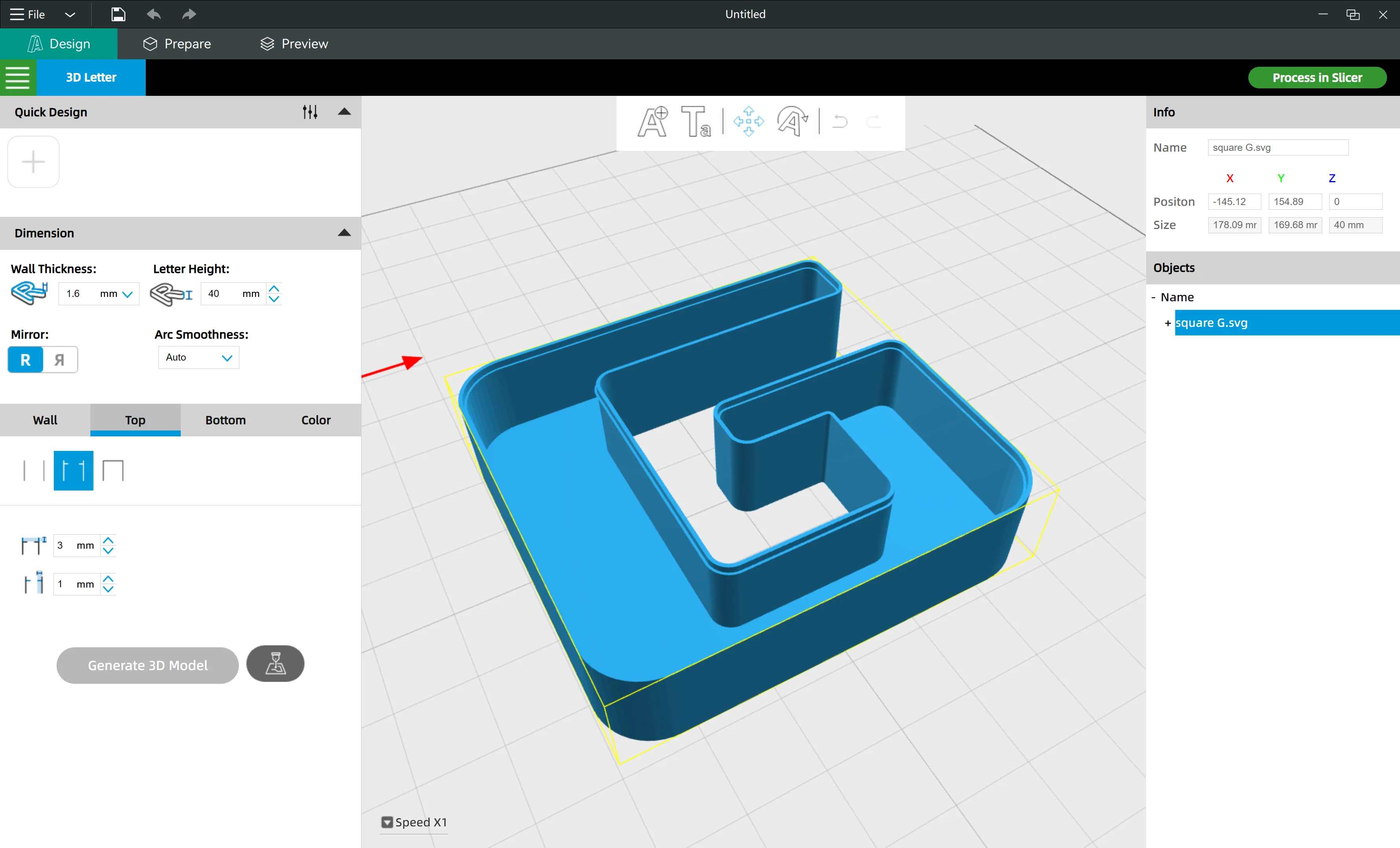
- Top section: choose the second option to generate a slot for placing the acrylic panel
- Bottom section: choose the full face bottom option to generate the enclosed bottom for placing the LED light stripe
¶ 2. Channel & Face in one piece
3D printing technology gives more freedom to fabricate unique texture and style of the channel letter face.
¶ Design Tips
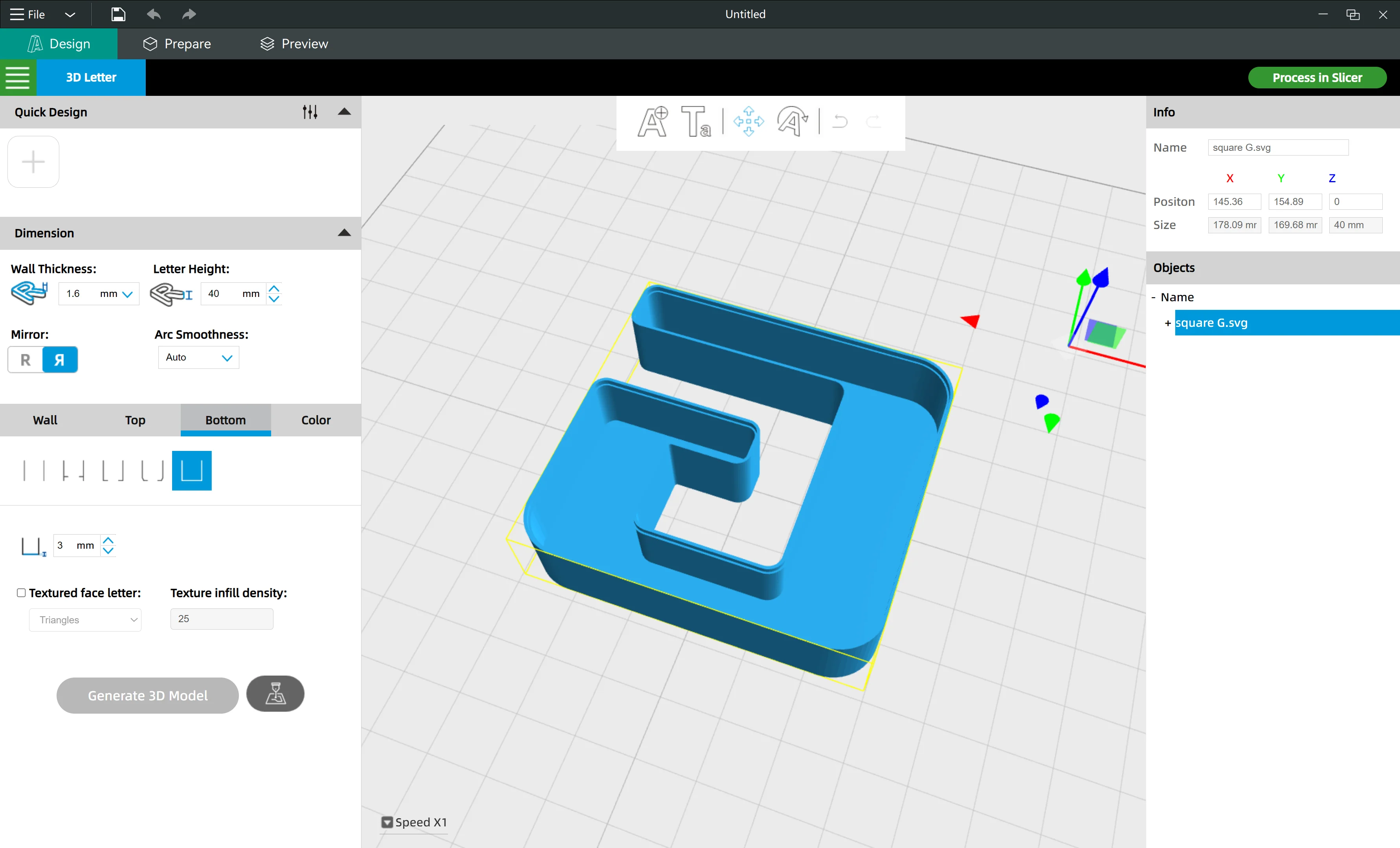
- Mirror the letter
- Top section: choose the second option to generate a slot for placing the backing panel
- Bottom section: choose the full face bottom option to generate the enclosed bottom(as this is a mirrored letter, so the bottom here is actually the face of the channel letter)
¶ 3. Slice Tips
¶ 3.1 3D print a hollow face(bottom)
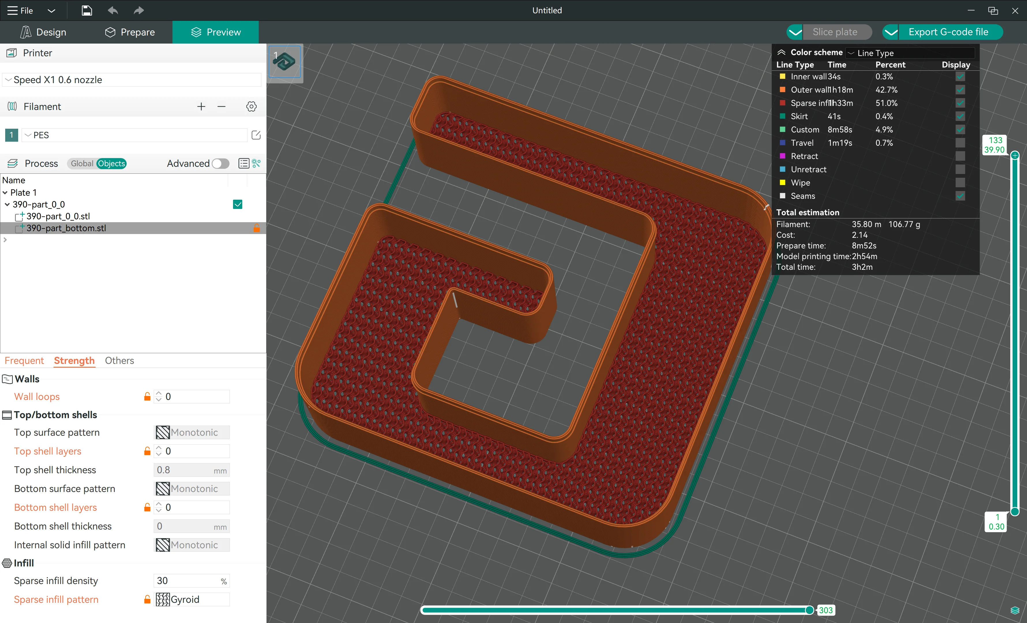
- Switch the slicer to "Objects" mode
- Click the "****_bottom.stl" file in the STL file list
- Set the "Strength" parameter: Wall loops: 0, Top shell layers: 0; Bottom shell layers: 0; Sparse infill density: 30; Sparse infill pattern: Gyroid
- Click the "Slice plate" button to preview the G-code file
- You now get a hollow face channel letter
By switching the "Sparse infill pattern" and "Sparse infill density", you can compare and choose the ideal textured face for your unique channel letter.
¶ 3.2 3D print a textured face(bottom)
|
|
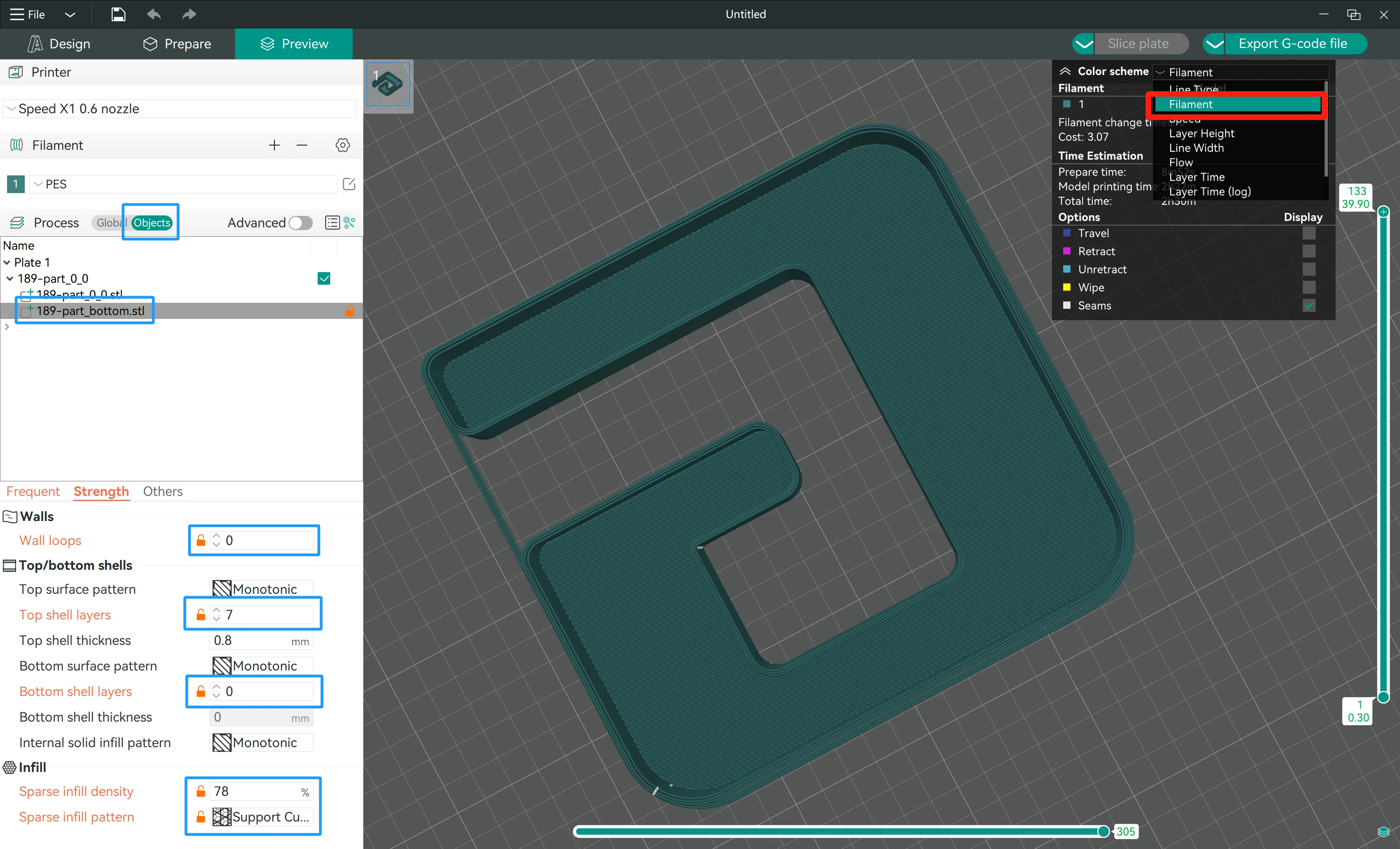
- Switch the slicer to "Objects" mode
- Click the "****_bottom.stl" file in the STL file list
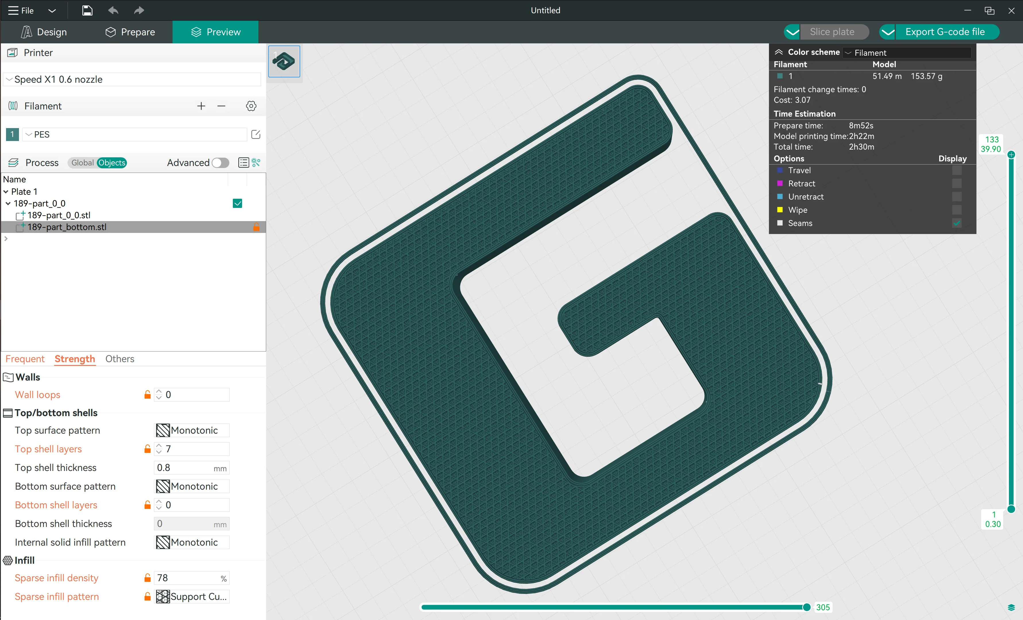
- Set the "Strength" parameter: Wall loops: 0, Top shell layers: 7(it depends on the bottom thickness you generated); Bottom shell layers: 0; Sparse infill density: 78; Sparse infill pattern: Support cubic
- Click the "Slice plate" button to preview the G-code file
- You now get a textured face channel letter
To get an excellent texture, you need to choose a proper "Top shell layers" number, so that you will have proper 2~3 infill layers.
But why do you need 2~3 infill layers?
Because too many infill layers might bring overhand or bridging challenges, that will lead to 3D print quality issues.
How to calculate the "Top shell layers" number?
Top shell layers = bottom STL thickness÷layer thickness - 2 (or 3)
For the case above, it is 3÷0.3-3=7
¶ 3.3 3D print a solid infill face(bottom)
Consider the hard to accomplish leveling accuracy needed to 3D print a perfect first layer, we don't recommend you to treat solid face (bottom) as a mainstream or featured product for your clients.
You might encounter unsatisfying face(first layer) quality randomly.
 |
 |
- Switch the slicer to "Objects" mode
- Click the "****_bottom.stl" file in the STL file list
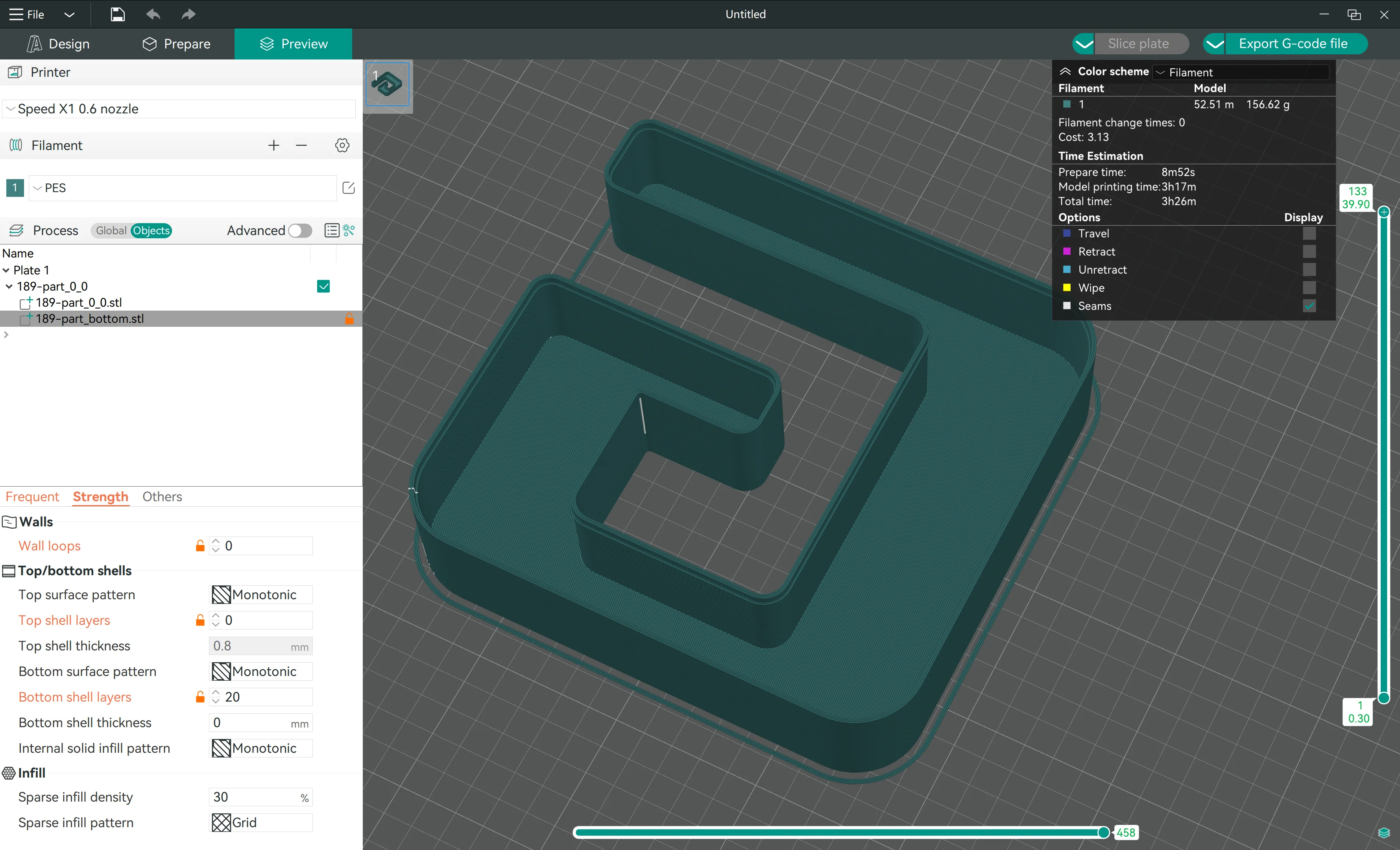
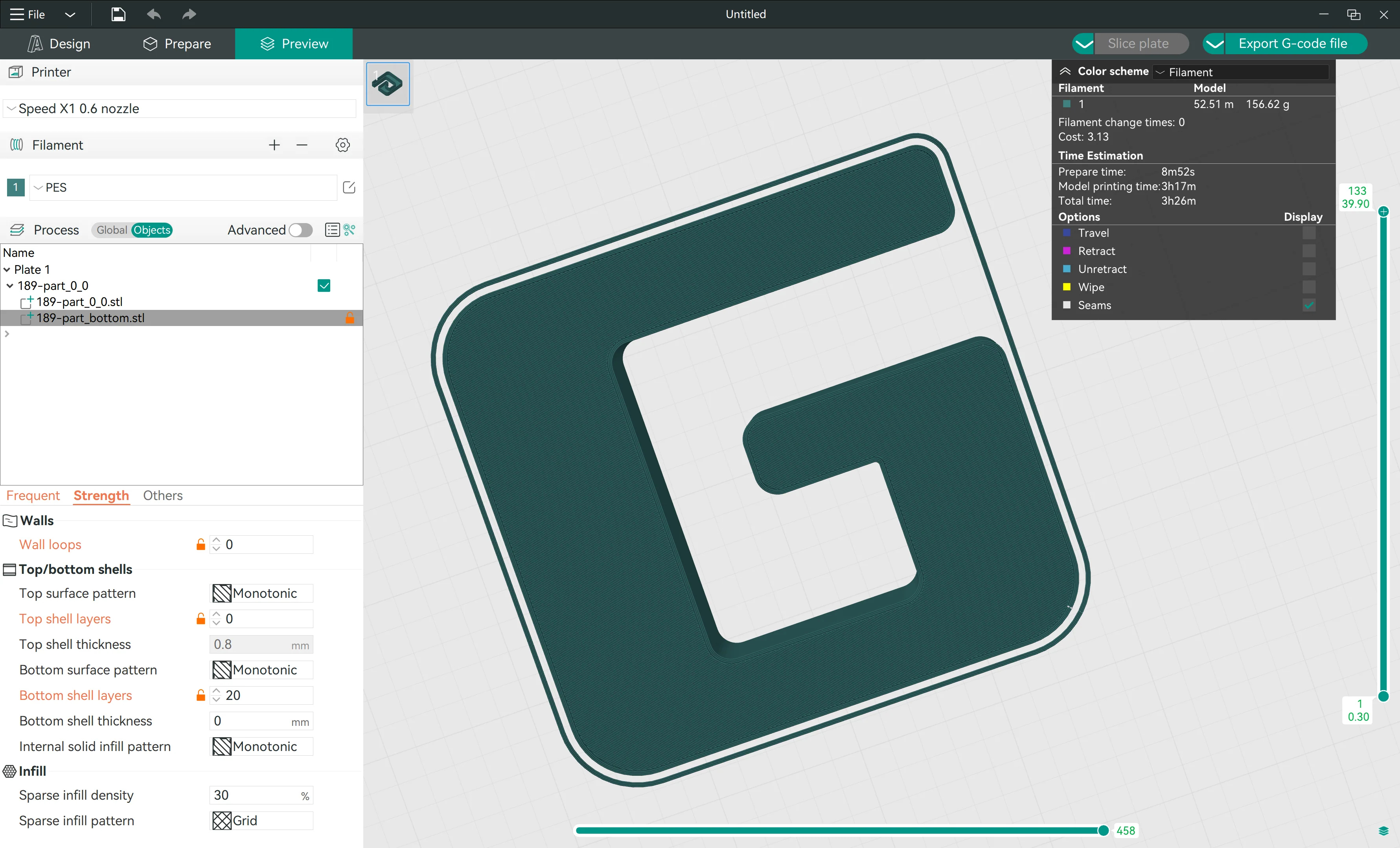
- Set the "Strength" parameter: Wall loops: 0, Top shell layers: 0; Bottom shell layers: 20 (any number to make sure the bottom layers are thicker than the thickness of the bottom STL file(3mm default)); Sparse infill density: default; Sparse infill pattern: default
- Click the "Slice plate" button to preview the G-code file
- You now get a solid face channel letter