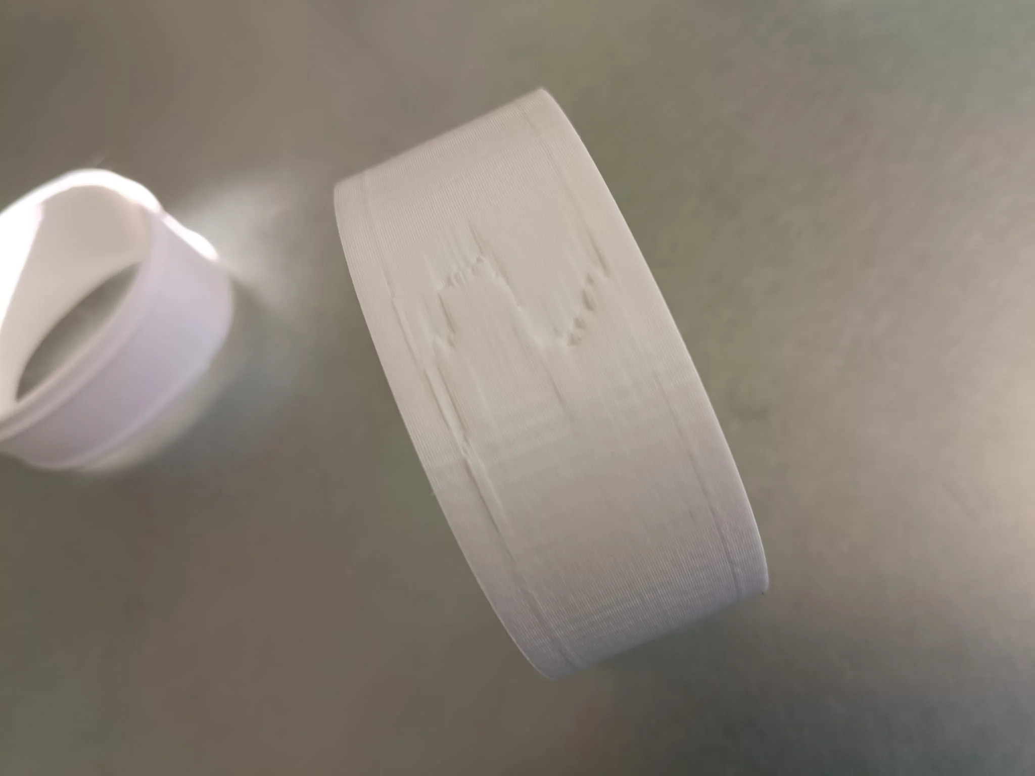
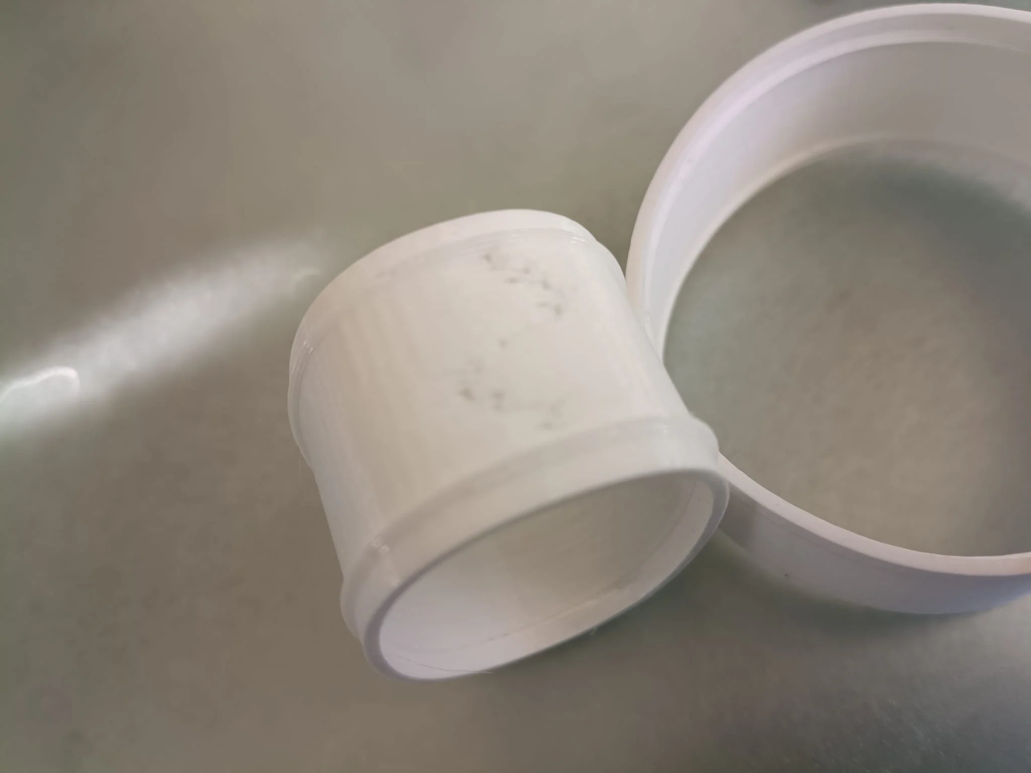
If you encounter print flaws like these, please follow the guides on this page to minimize them:
 |
 |
¶ 1. Understand seams
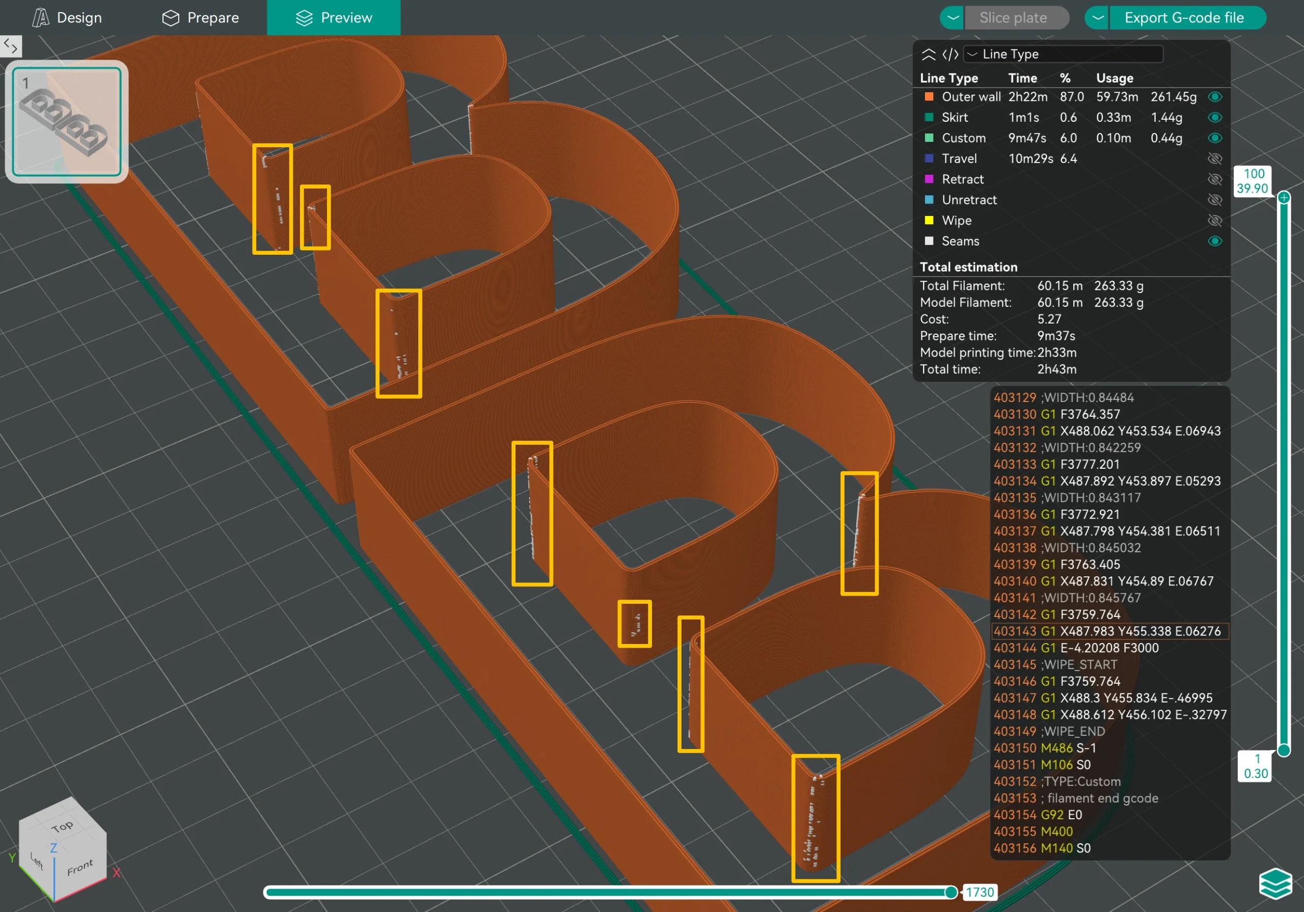 |
After slicing, you will see these white spots on the surface of the sliced G-code file. These are the seam positions. Every white spot is the start and end point of a print path. It will lead to a print flaw. |
But you can let the slicer generate it with sharp corners to minimize the impact on surface smoothness.
Or you can use the "seam painting" feature to let the slicer generate the seam in an invisible position of the letter.
¶ 2. Slicer will automatically generate seams in sharp corners
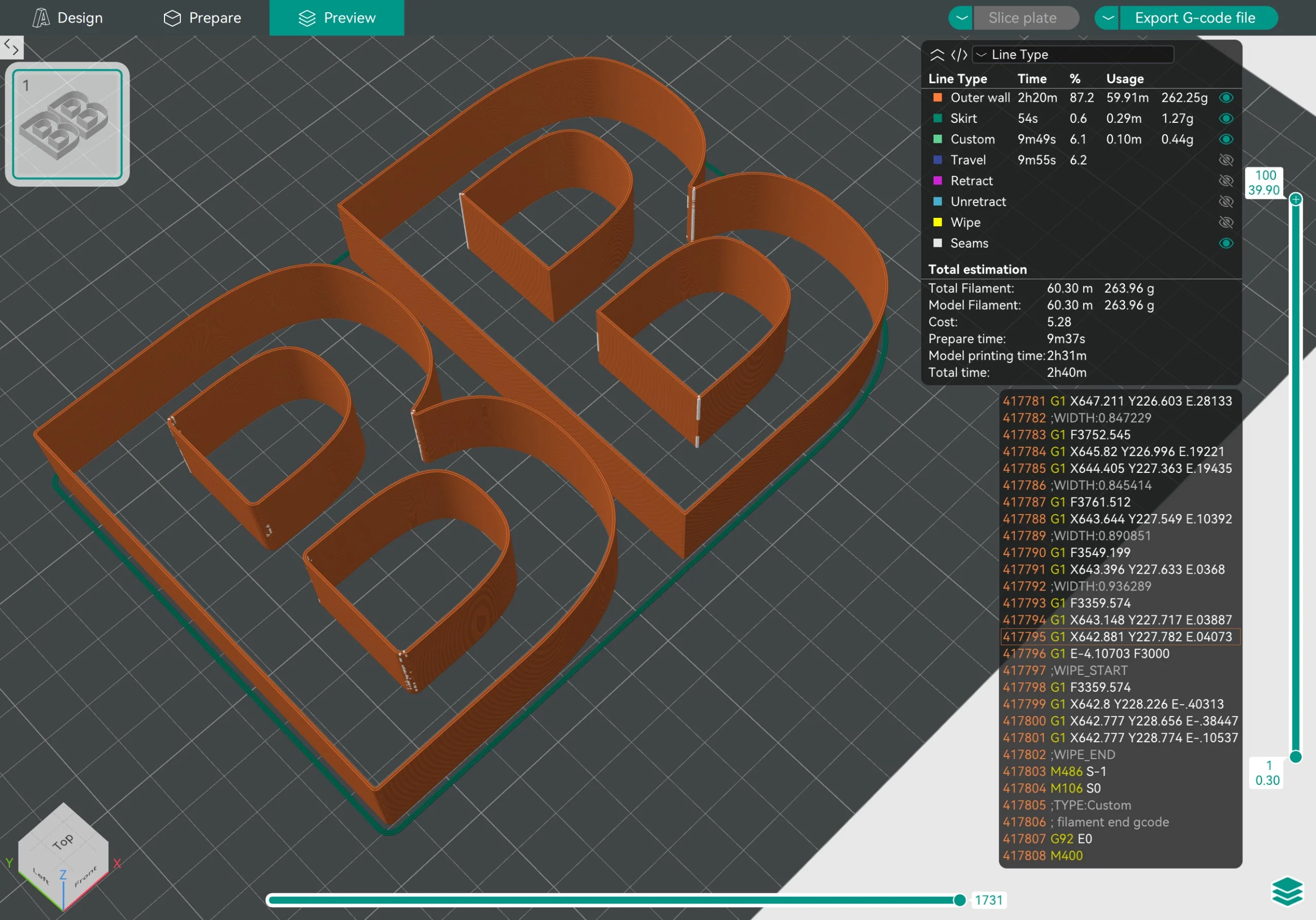
In this screenshot, the right B letter: we did not add big ratios for the corners, so you can see the slicer generates the seam precisely at the sharp corners.
The right B letter will look much better than the left one.
¶ 3. Manually define the seam position for no-sharp corner 3D models
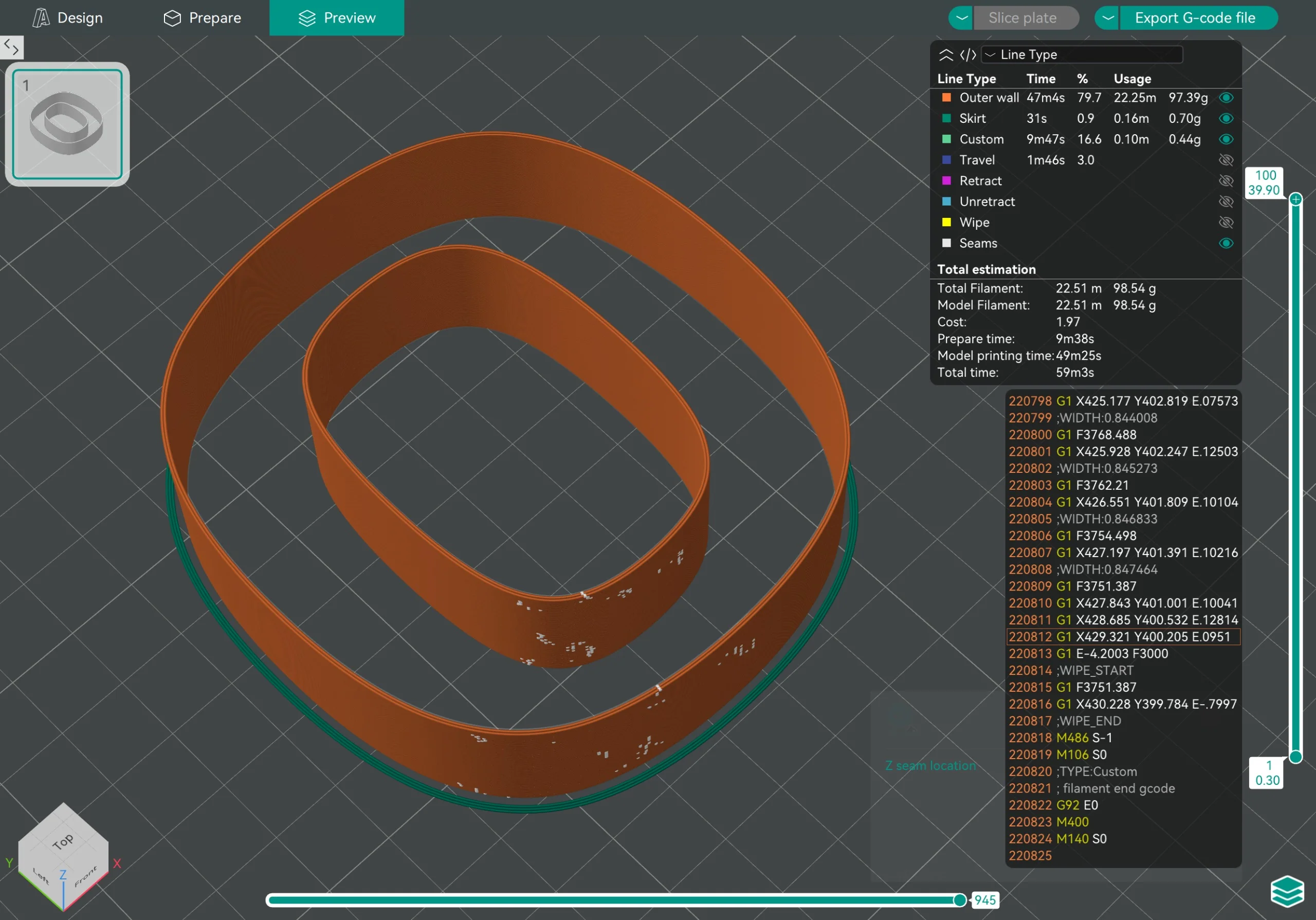
But if you are dealing with an "O" letter, there are no-sharp corners at all.
So the slicer generates the seams randomly, like in this screenshot.
It looks ugly.
For these "no-sharp corner" cases, you have to manually define the seam position as I mentioned, and use the "seam painting" feature.
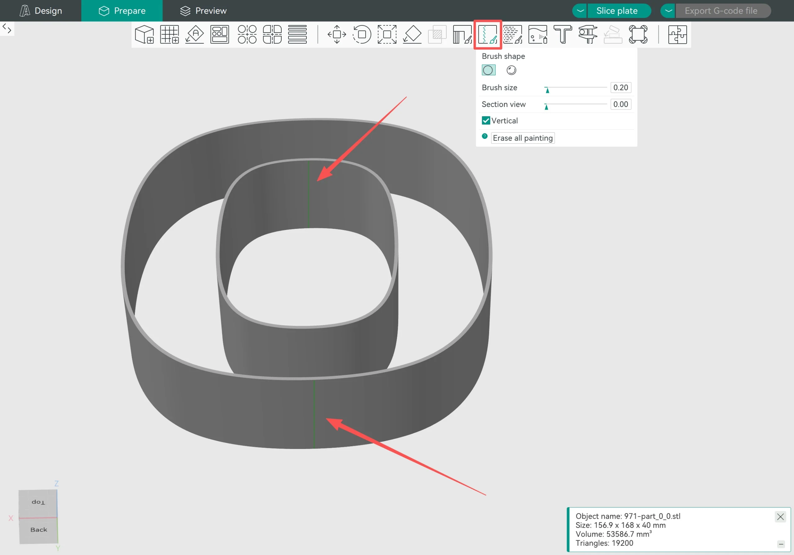
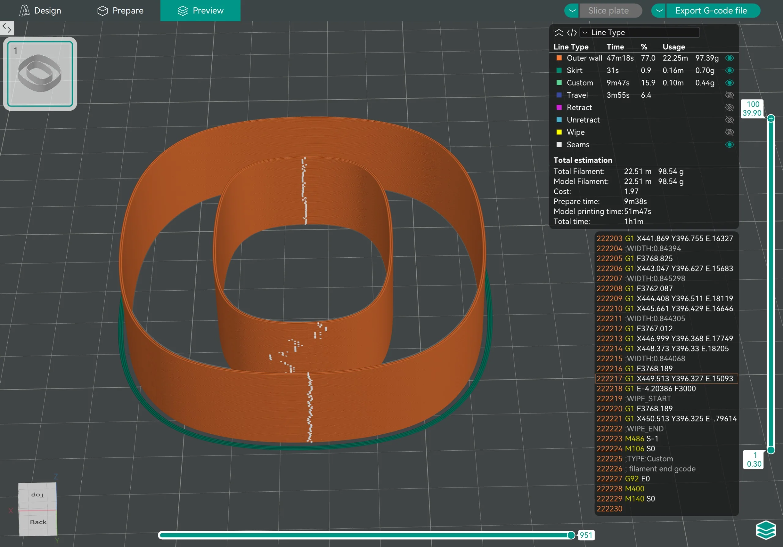
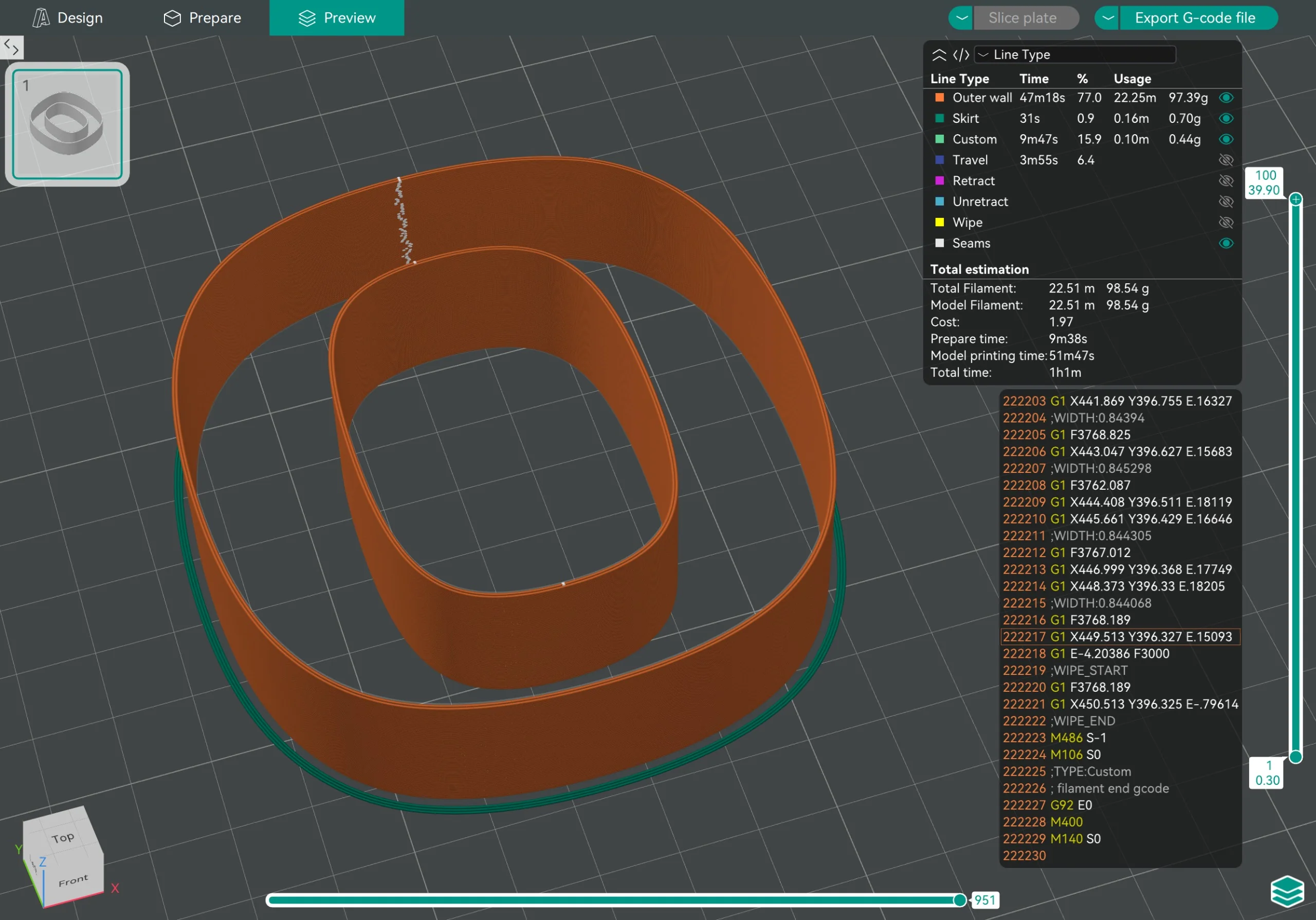
In the prepare interface, we select the "seam painting" function, select the "vertical" option, and paint on the surface of the 3D model (very thin green lines). The seams will appear at these two positions, where they will be invisible after installation.
|
|
¶ 4. Use the "scarf joint seam" feature to make the seam even better
 |
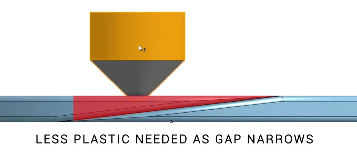 |
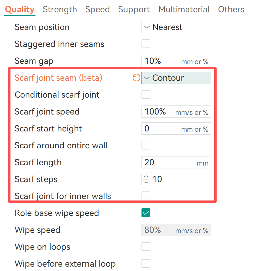
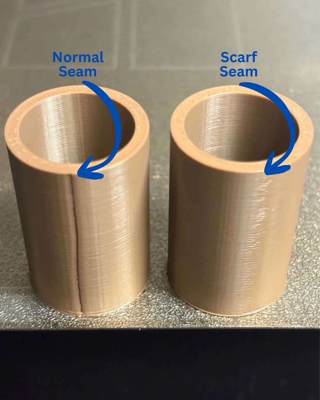
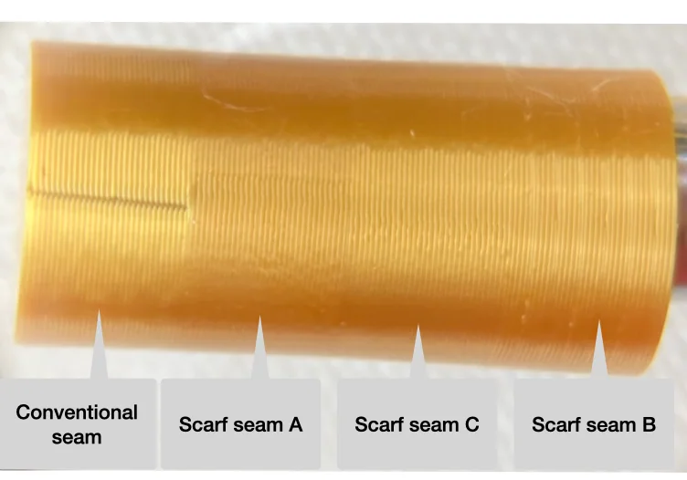
“Scarf joint seam” is a 3D printing technique that minimizes the visible Z-seam by angling the start/end points of a perimeter layer, creating a tapered, overlapping joint rather than a "butt joint". This method reduces "zits" and improves surface quality, especially on curves, by tapering the filament flow to create a smoother, less noticeable transition.
|
Optimal Scarf Seam Settings These settings are commonly recommended for best results: Seam Position: Scarf Joint Seam: Enabled (select Smart Scarf Seam Application: Enabled (uses scarf on curves, standard on corners). Scarf Length: 25mm Scarf Steps: 10 to 20 Scarf Joint for Inner Walls: Enabled (helps improve consistency). Wall Printing Order: Outer Wall Line Width: 150% of nozzle diameter Outer Wall Speed: 75~100mm/s (slow speeds help control the flow). |
 |
 |