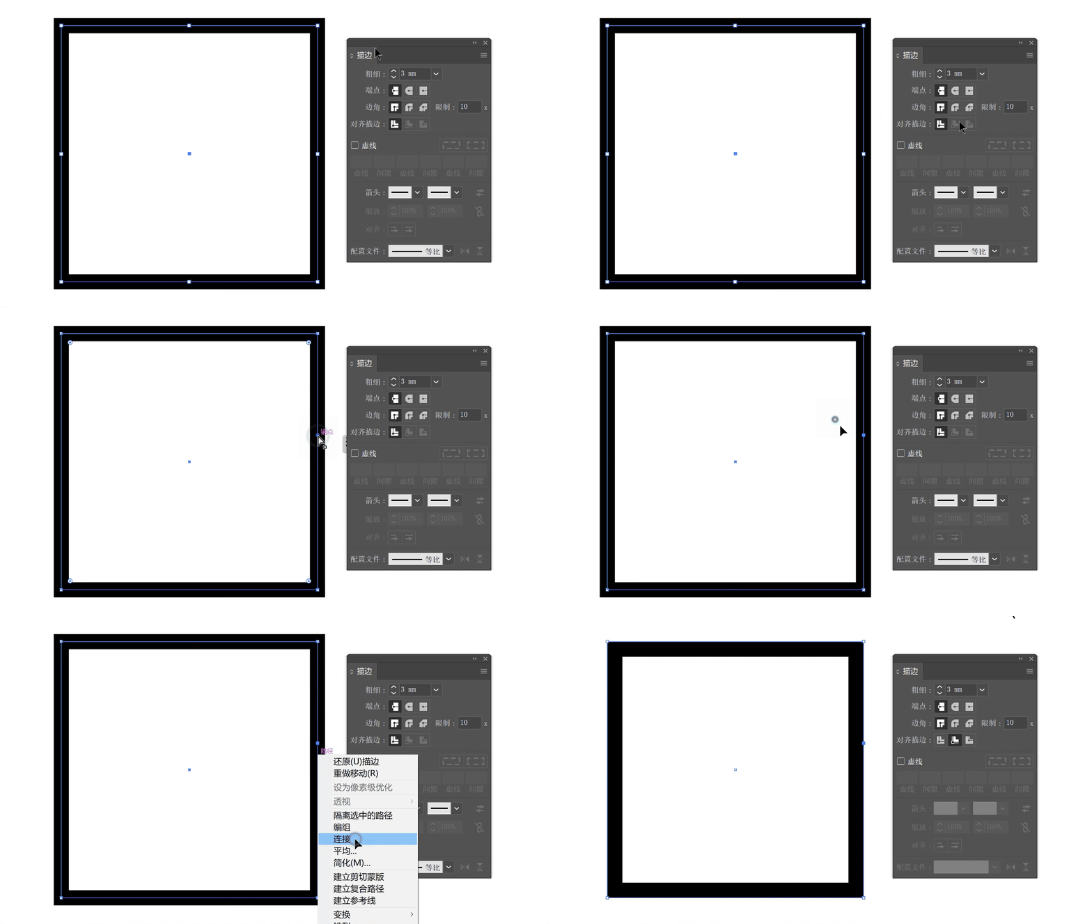
To better preview the 3D model wall thickness in graphic design software, we recommend you to set the stroke with the same wall thickness you will generate in FormLetter software.
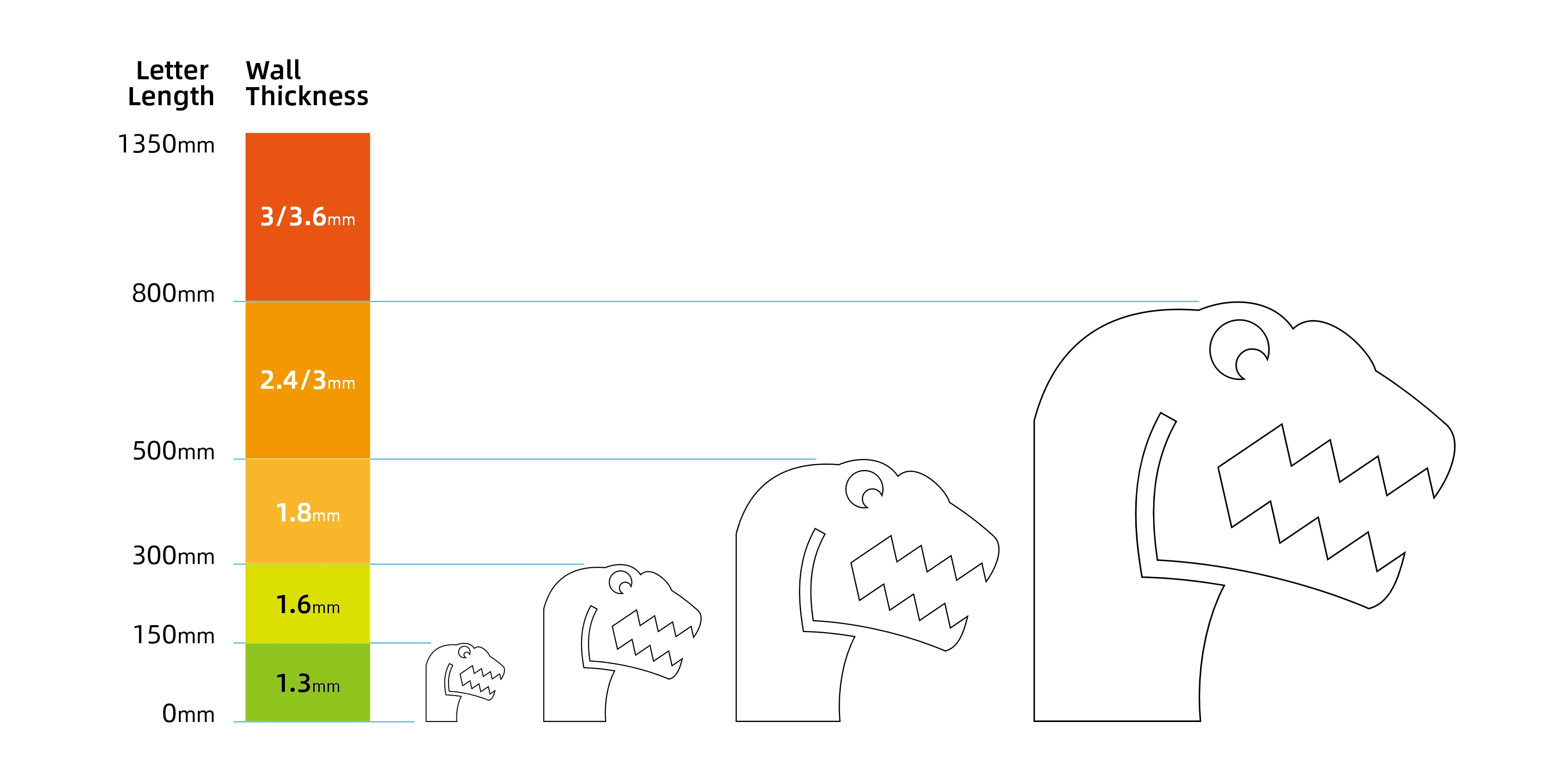
This is a reference table to indicate the relationship between letter length and 3D model wall thickness:
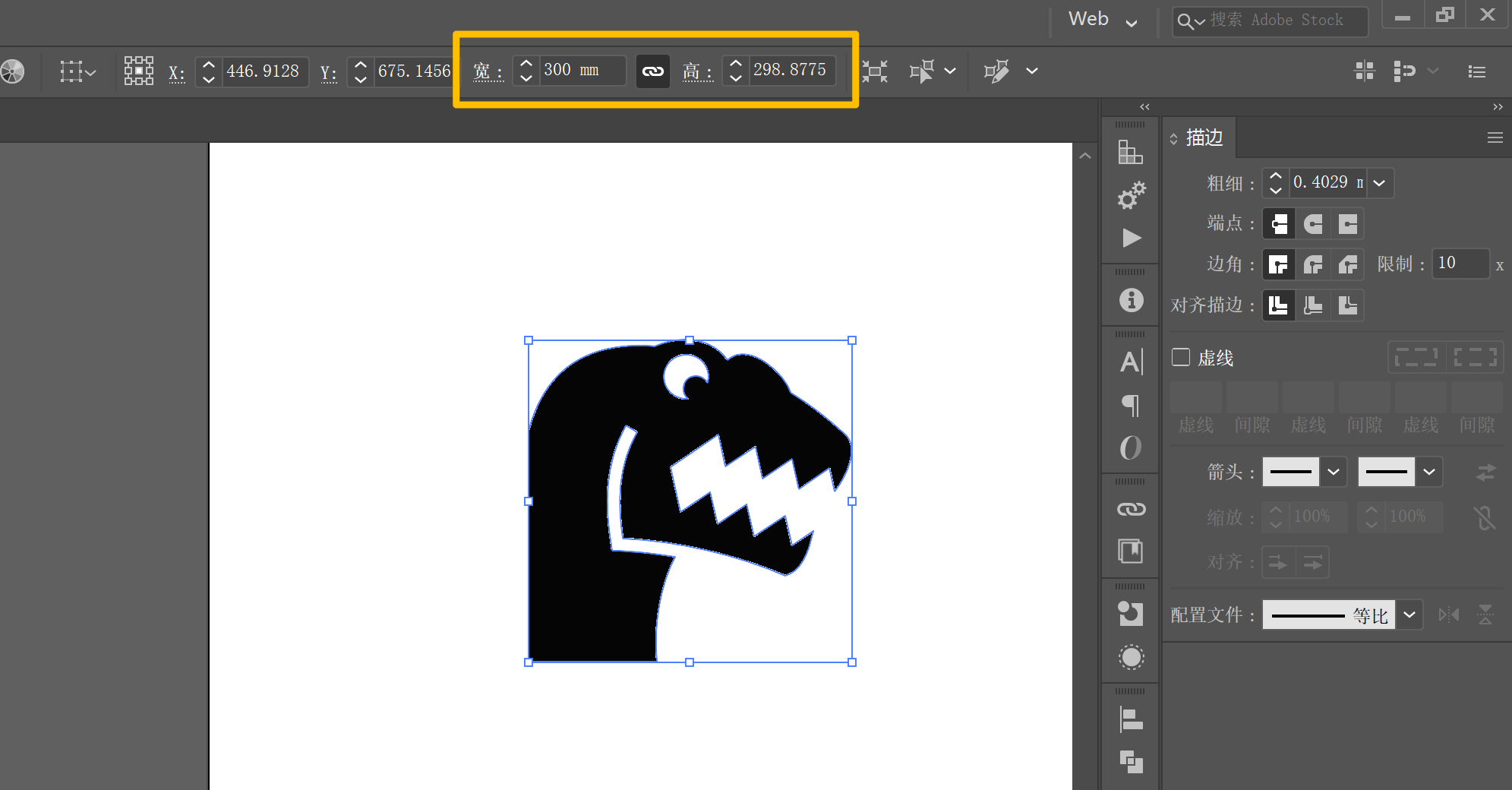
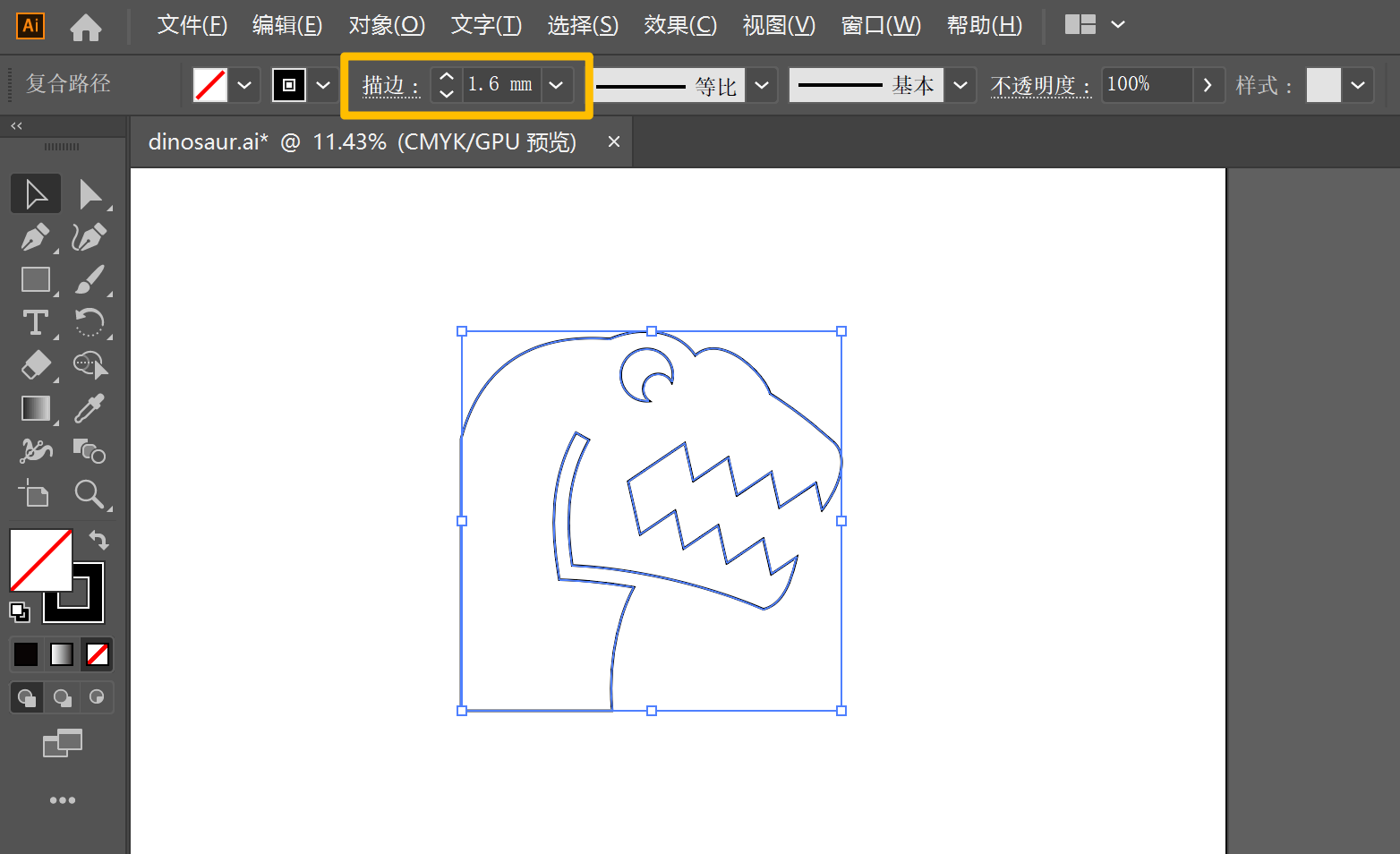
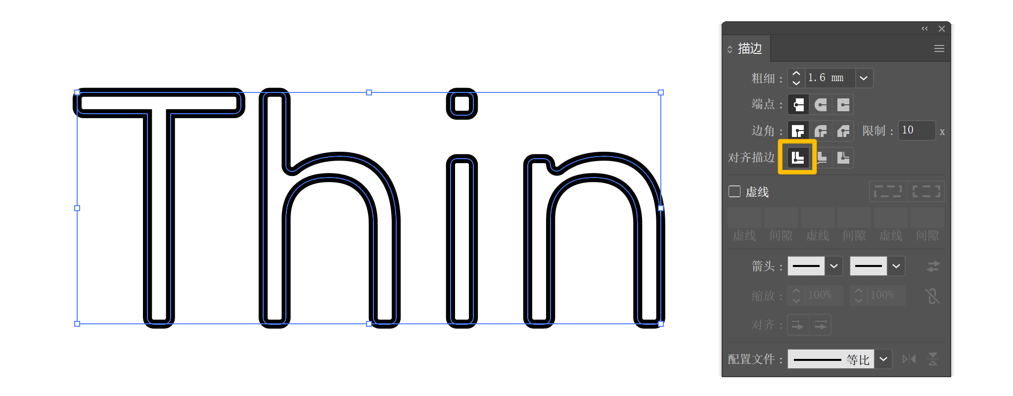
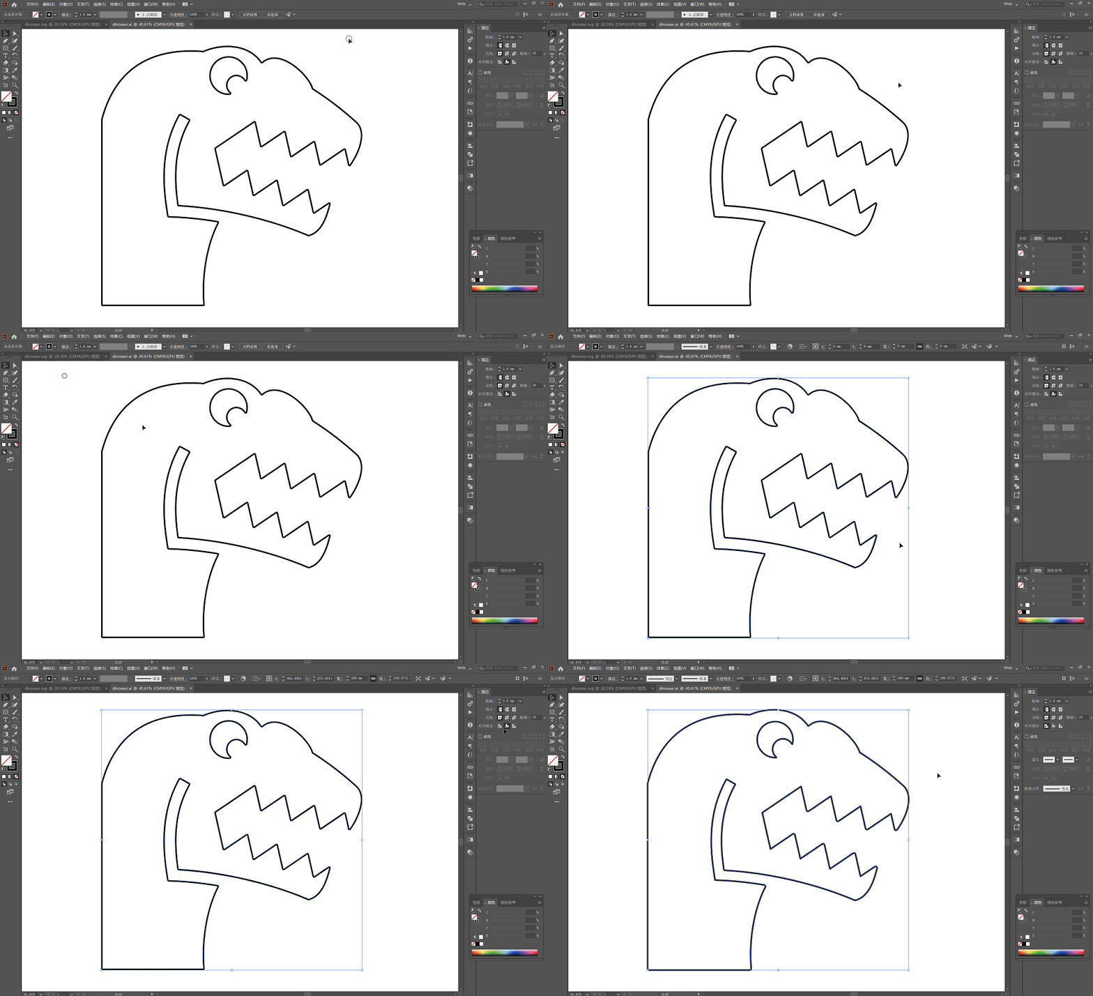
This sign is around 300mm in length, so here in Adobe Illustrator software we set the stroke width 1.6mm:
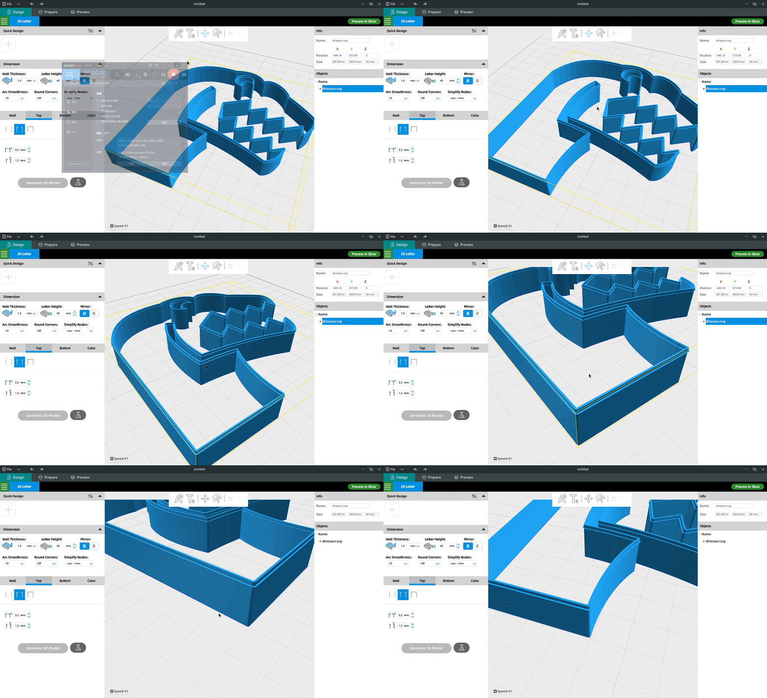
FormLetter software generates a 3D model with a wall thickness inside the outlines.
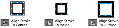
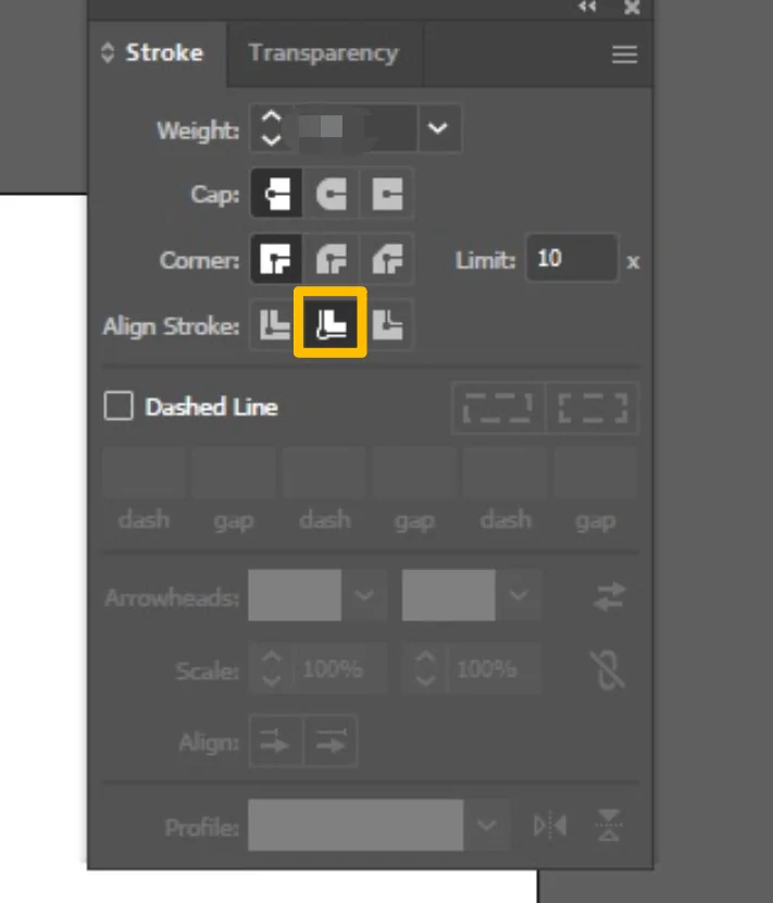
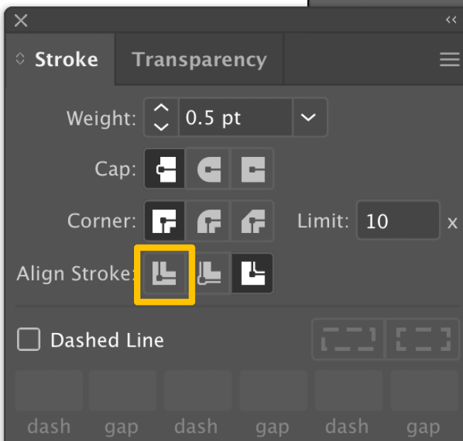
So switch the "Align Stroke" option to "Align Stroke to inside" will help you to preview the real appearence of the signage.
Tip: Why does "align stroke to inside" help you to preview the letter?
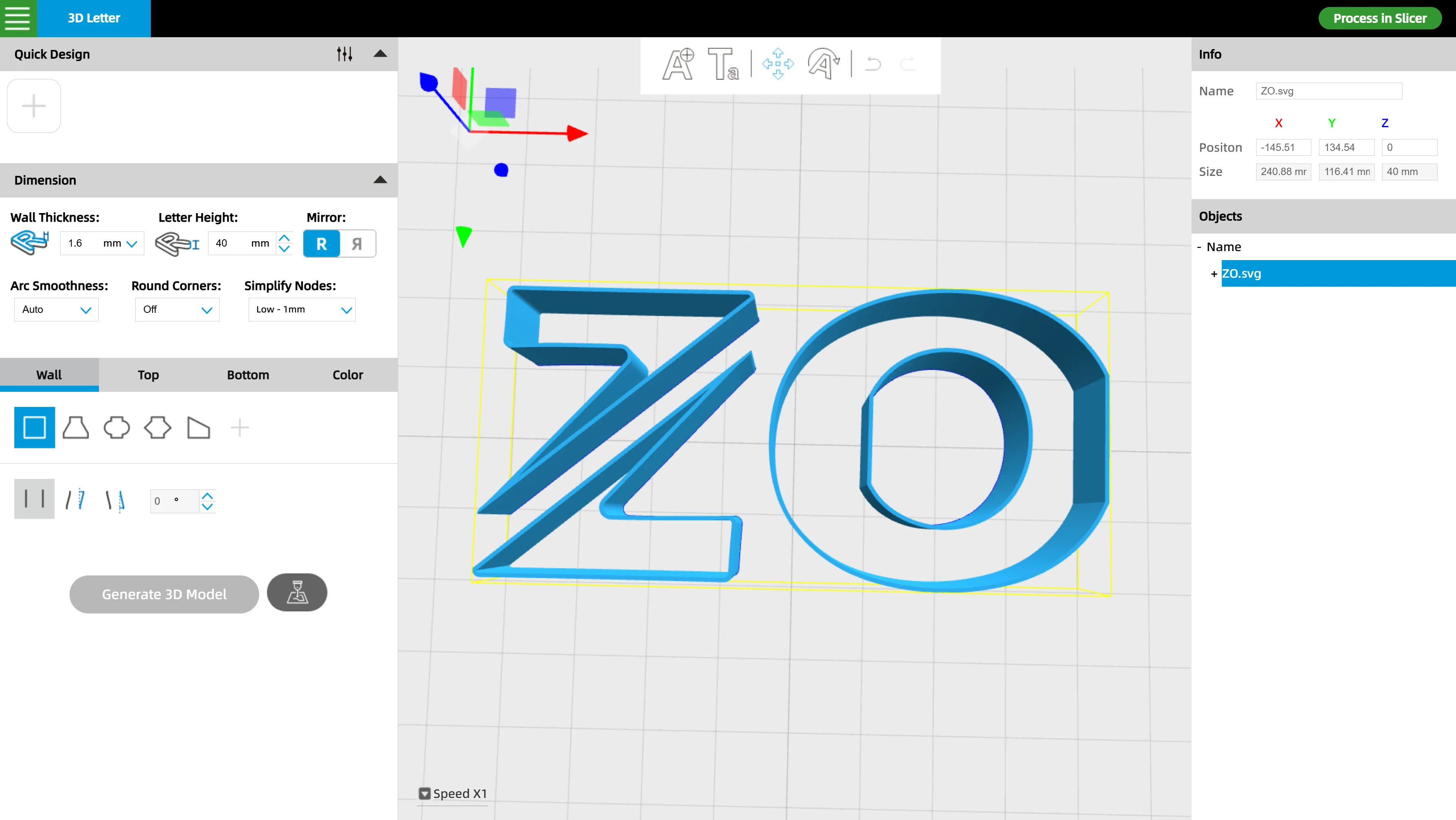
As what's shown below, the wall thickness is generated inside of the outlines:
in FormLetter software, it does not read the stroke width data even you have set the width in graphic design software
FormLetter will generated the wall thickness at the inboard of the outline
The "Align Stroke To Inside" option helps to preview the inner gaps very well. It's good news when you are preparing a thin stroke font signage, you'll know if the gap is big enough for placing LED strips.
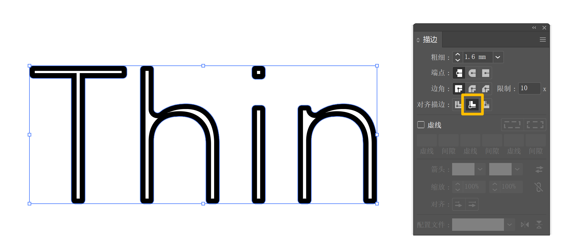
If you use "Align Stroke To Center" option, you might think the font or the design is good. But↓when you switch to "Align Stroke To Inside" option, you will know the wall will conflict with each other, not to mention palcing LED strips. This is what will happen when you import the SVG file into FormLetter software.
So the "Align Stroke To Inside" option allows you to spot problems earlier.
Troubleshooting: Cannot select the second "Align Stroke" option?
If you cannot select the second/third option of "Align Stroke"(the two options are gray and cannot be selected), it means the selected outline is not closed.
You have to close it, then try again.
To close the outline, please (Adobe Illustrator):
Method One: go to menu "Object" → "Path" → "Join";
Method Two: select the two nodes, right-click and choose "Join";
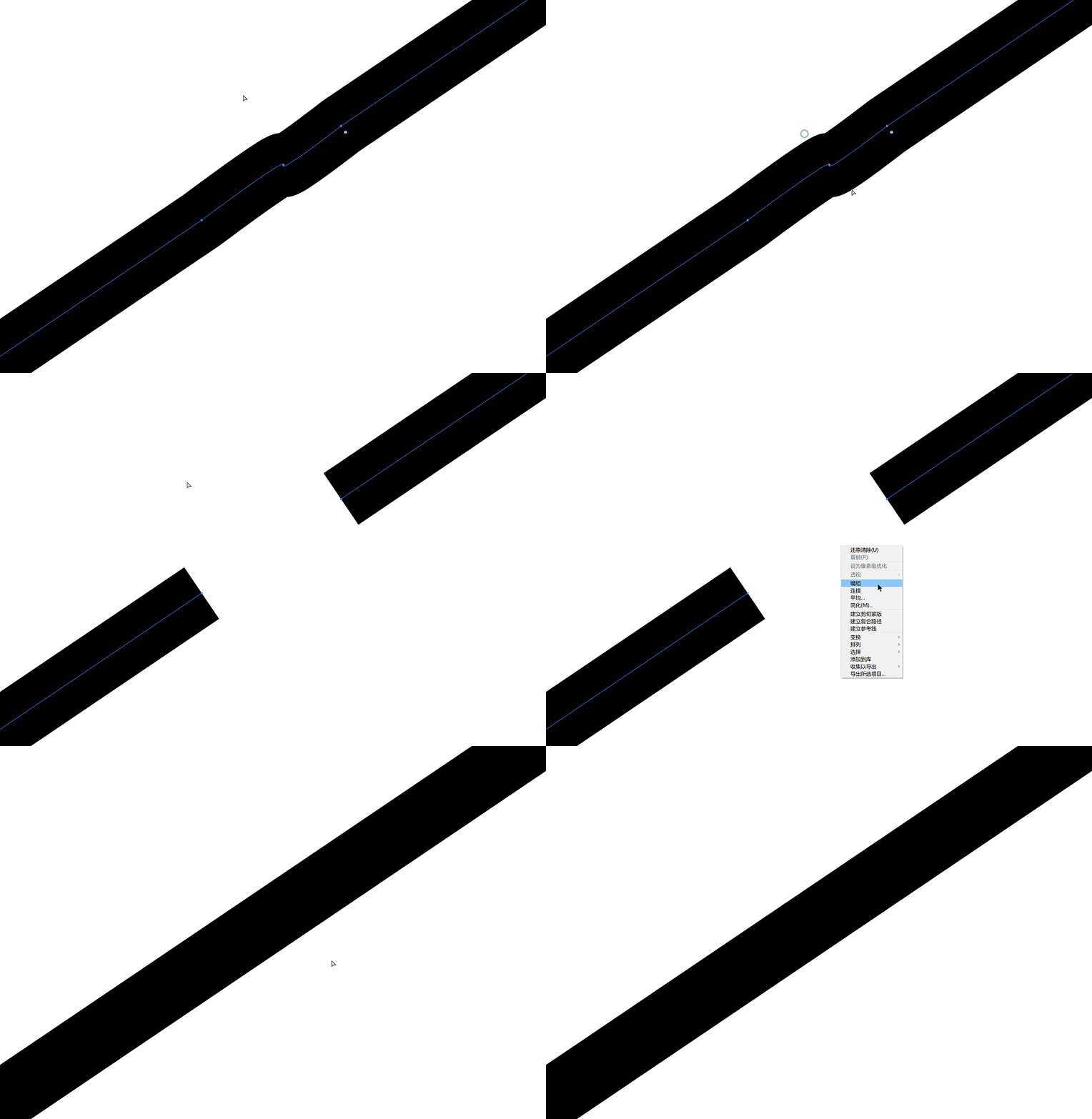
If your pattern is not closed, the FormLetter software will automatically close the open ends. In some cases it will lead to 3D model generation error.
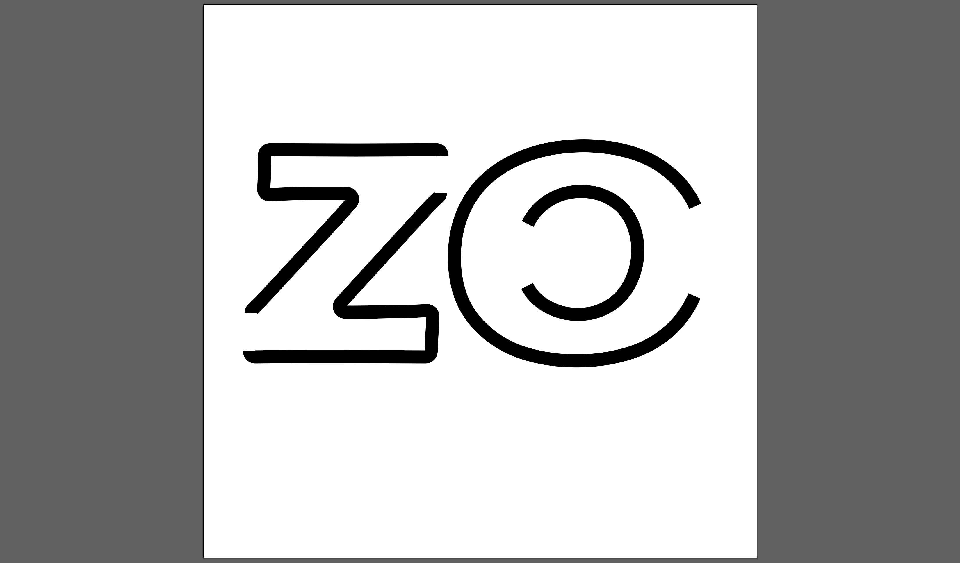
What happens if the outline is open in some areas?
export a SVG file with open outlines
FormLetter software will automatically close the open ends of a single path
Please press "Ctrl+J" to close the outlines to enable the second option in the "Align Stroke" panel, for better preview of wall thickness generation.
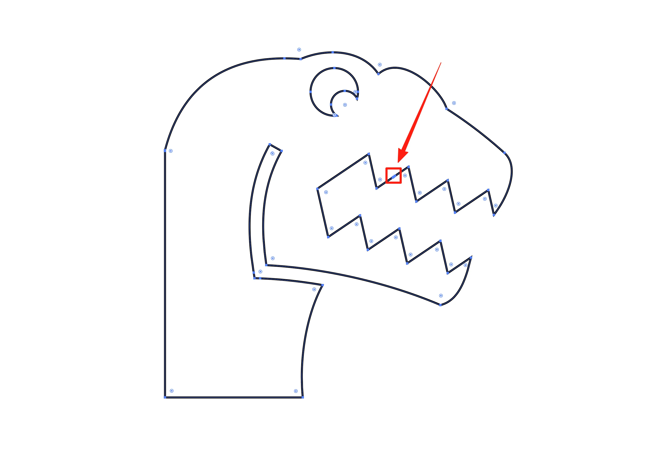
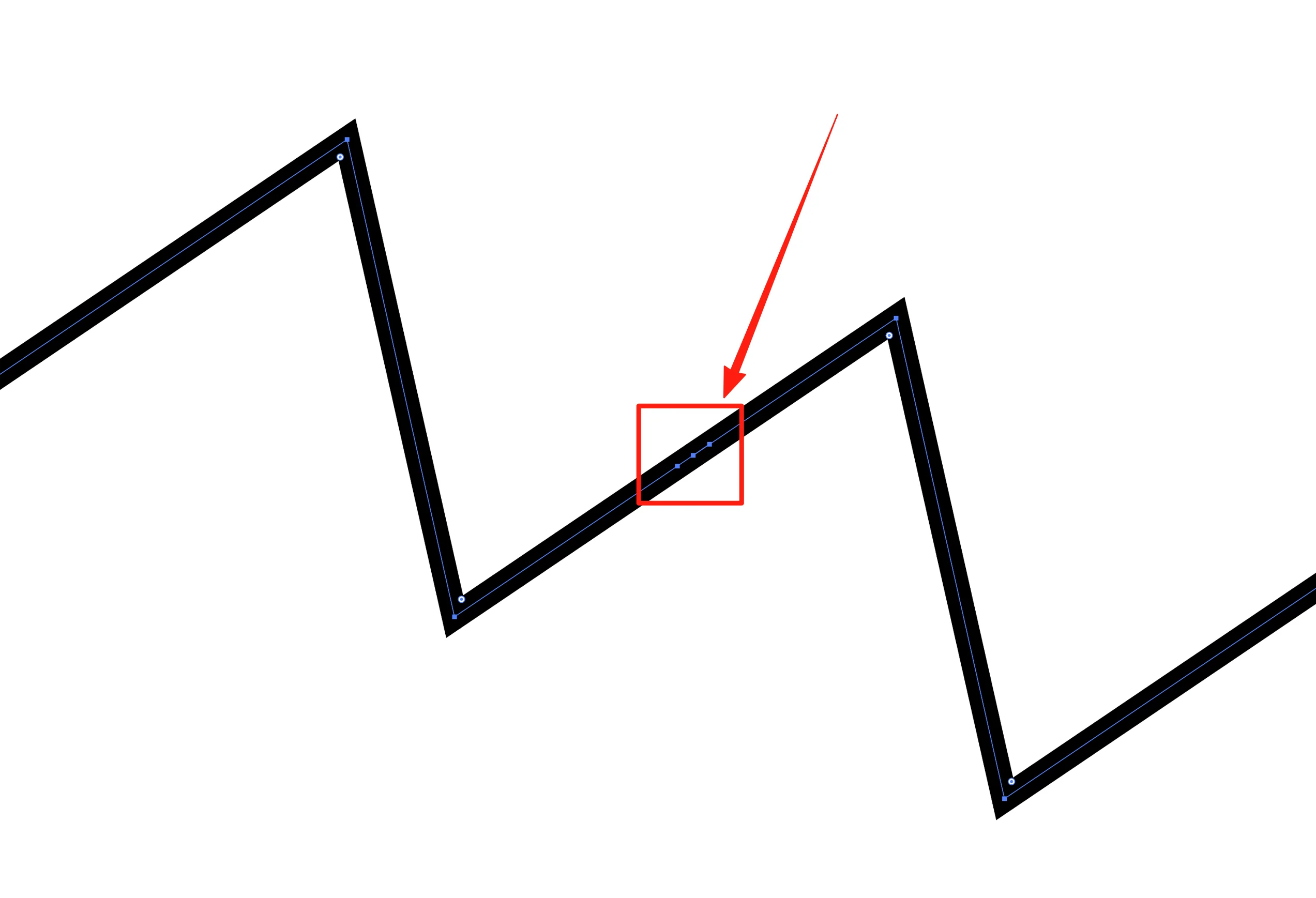
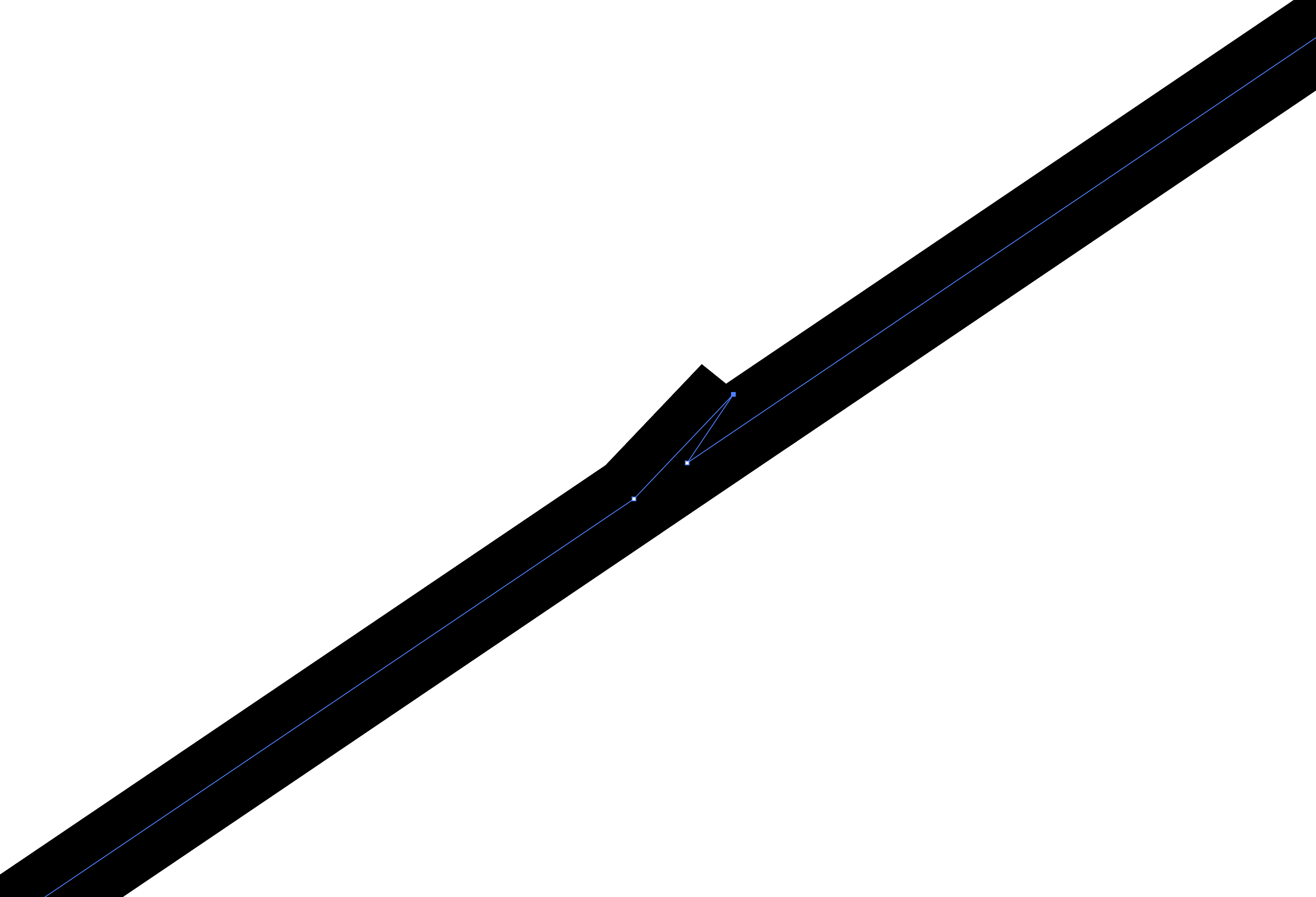
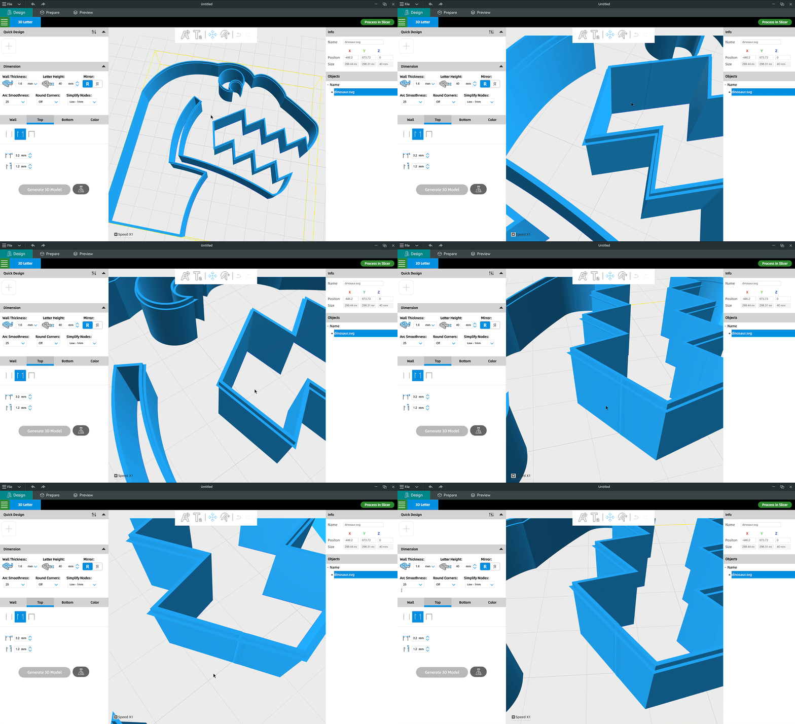
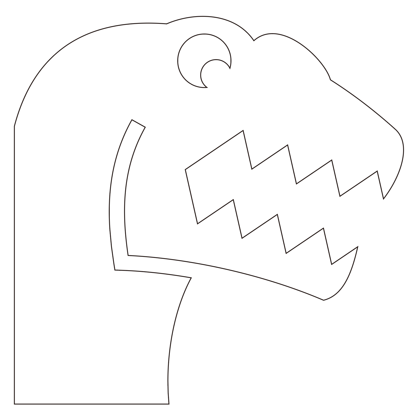
If you encounter a 3D model generation error like this, you can solve this problem by rounding the sharp corners:
Original SVG file with a lot of shrpe corners in it.
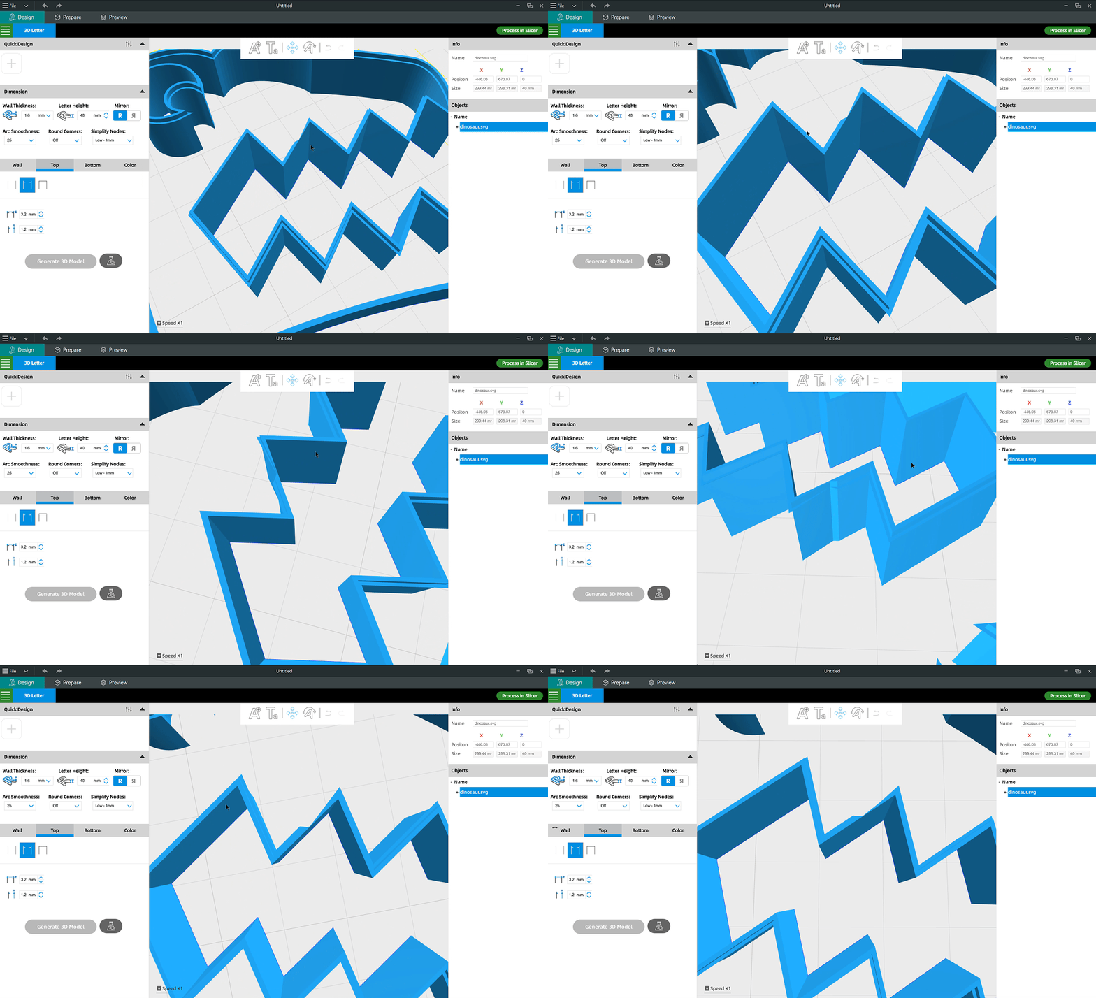
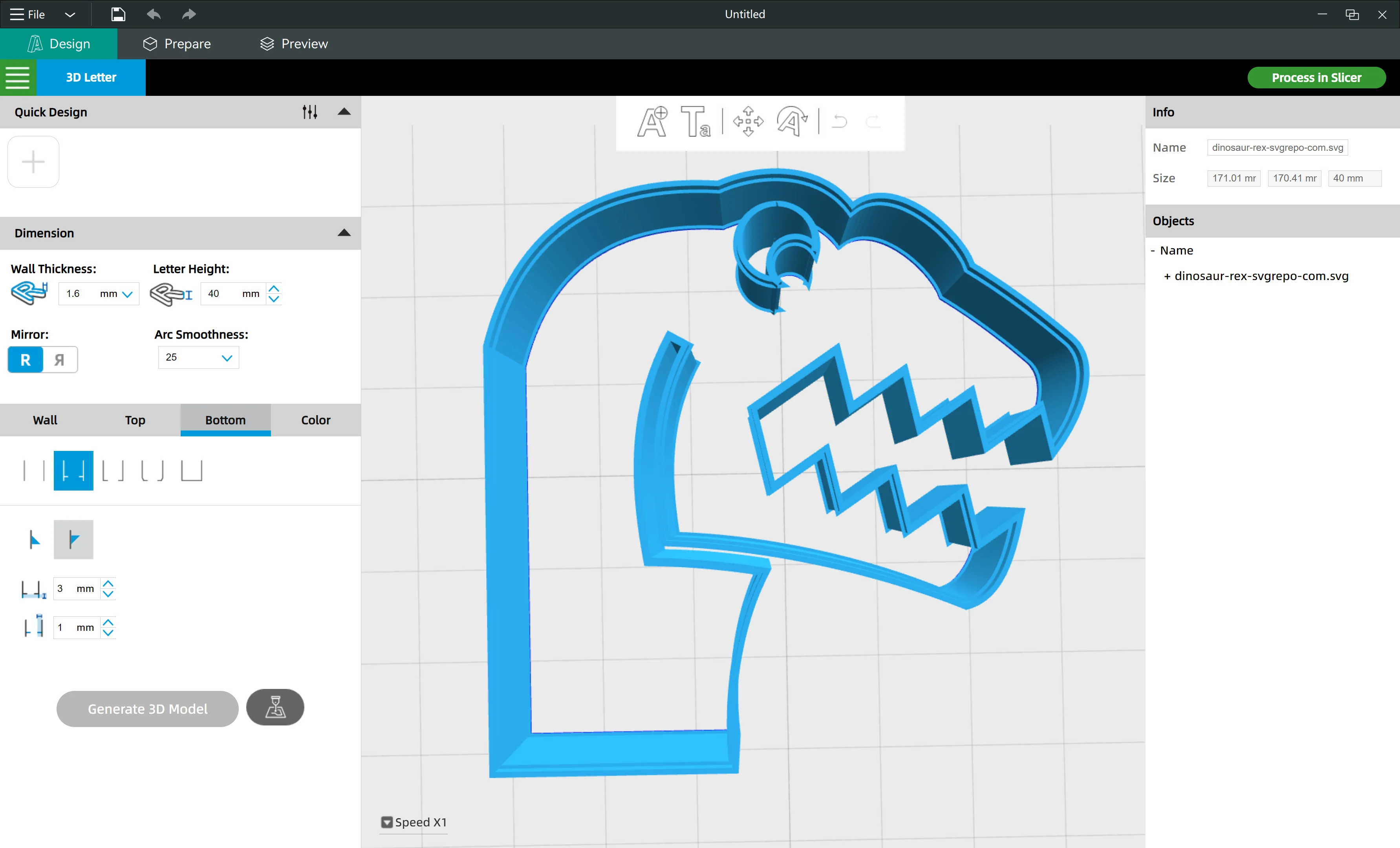
When you import the file into FormLetter, it looks good, but there are errors on the 3D model.
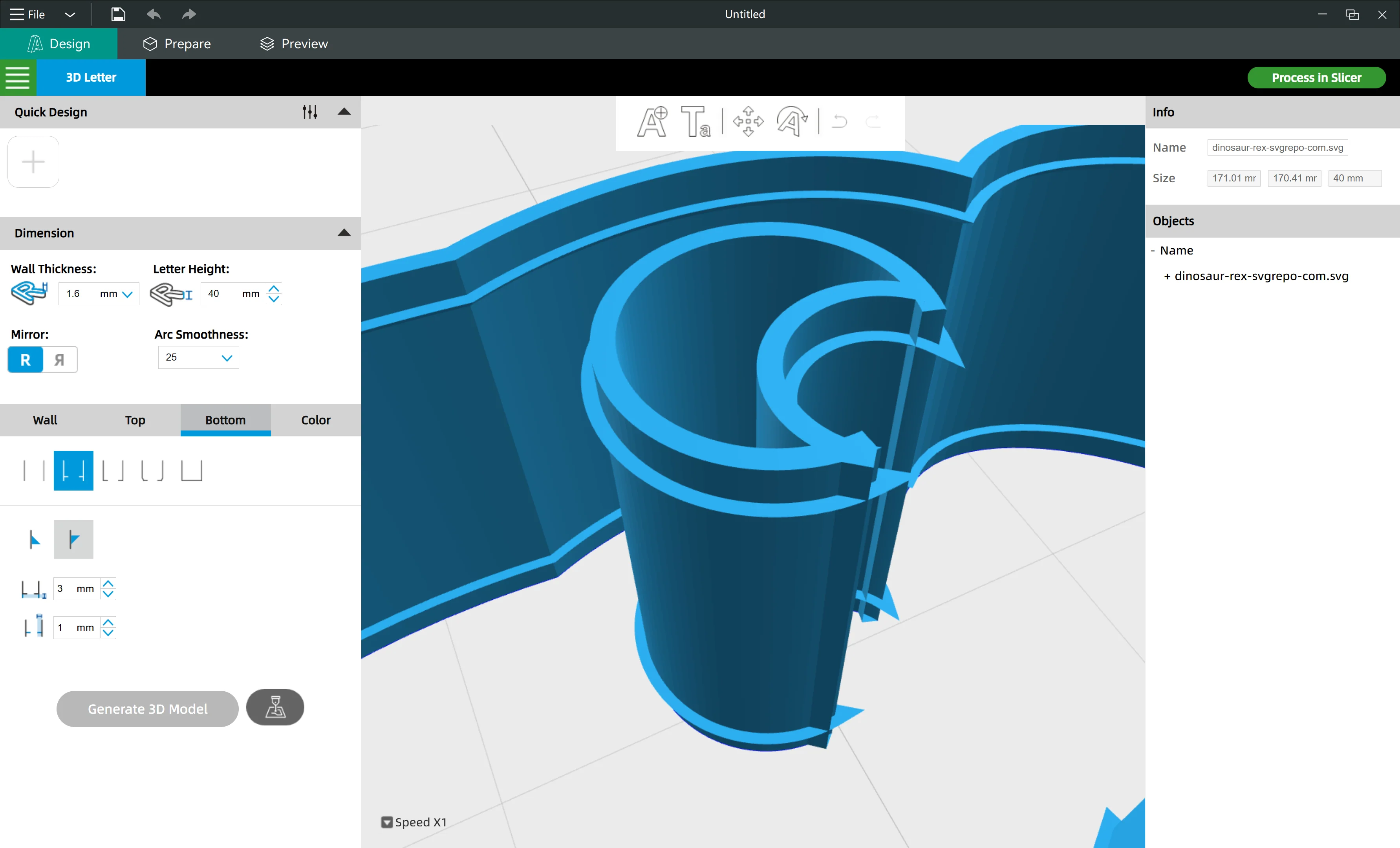
Zoom in the 3D view and take a close look at the corners, you will see those error. You cannot successfully slice these STL files or 3D print these structures.
This is a detailed guide showing how to properly round the corners with minimum change to the original graphic design:
Tips:
Convex corners: Increase the radius until the control ball (or manually drag the control ball) is inside of the corner, to make sure both inner and outer shapes are rounded.
Concave corners: Round the concave corners require just a very small radius.
Properly pre-process the SVG file is a guarantee of perfect 3D printing results
We recommend our clients to round the corners one by one manually instead of setting a global radius.
It looks time consuming, but actually saves a lot of time and effort by reducing 3D printing defects and failures.
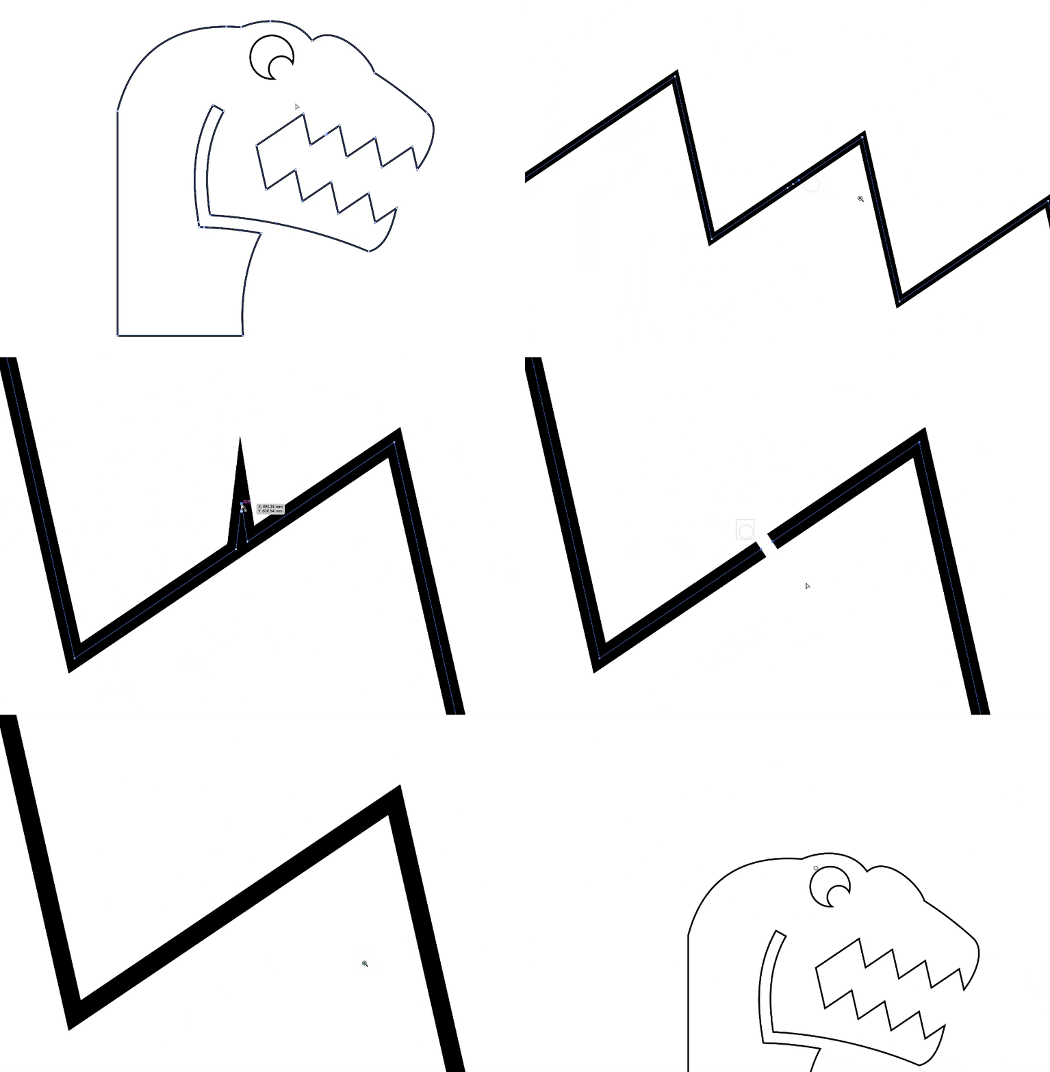
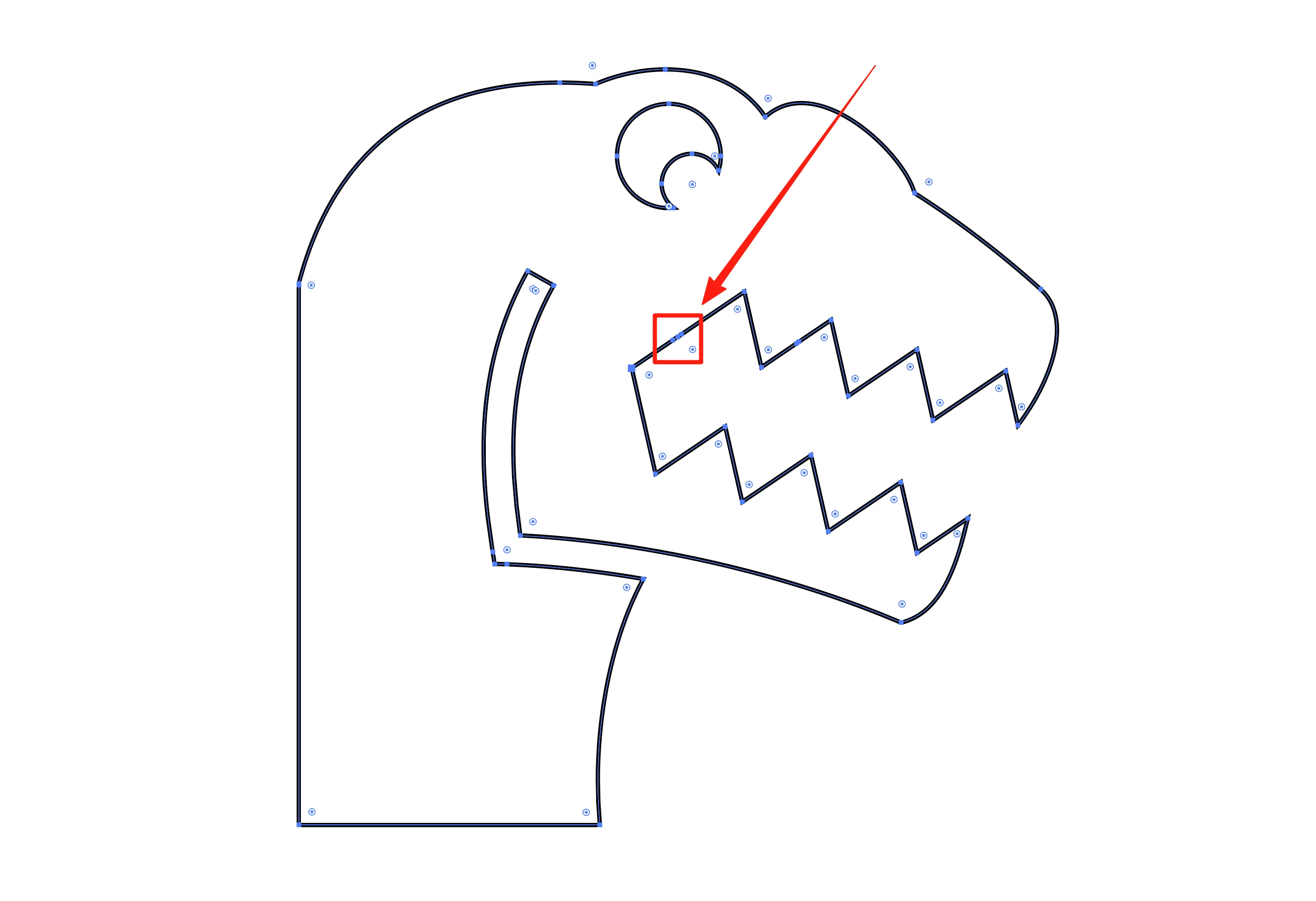
To generate smooth enough surface 3D models in as short time as possible, we recommend you to add or decrease the nodes on the outlines.
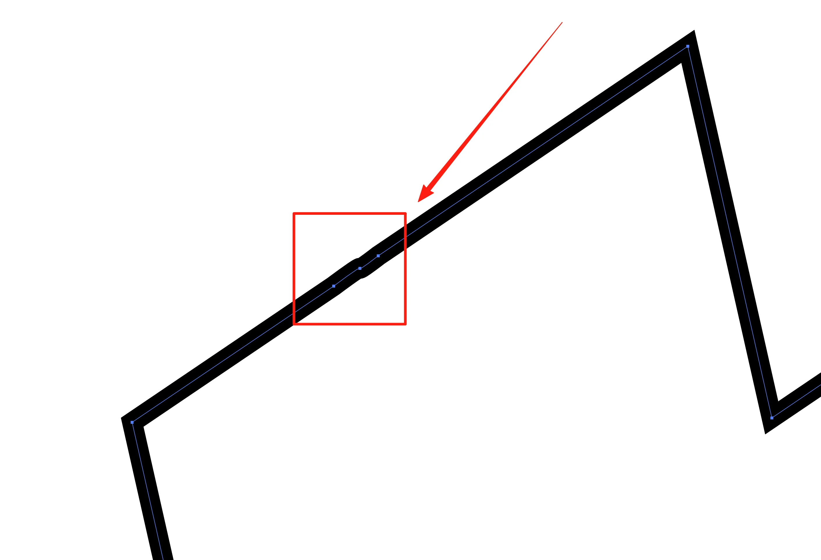
In this dinosaur case, we need to add some nodes to the arcs like this:
Pay attention to those arcs, not straight lines.
Reduce nodes
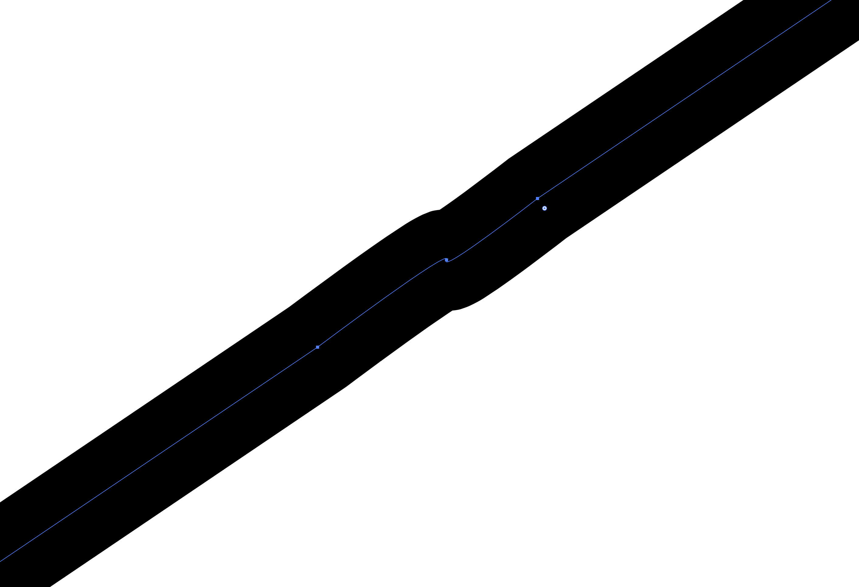
If there are many nodes in short arcs, it will increase 3D model generation time seriously.
So you have to reduce the nodes: enter menu "Object" → "Path" → "Simplify".
If after using the Simplify function there are too few nodes on the path, please manually add some nodes.
¶ 4. Switch stroke alignment option, then export SVG file
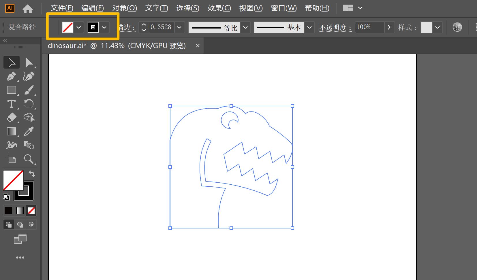
Before you export the SVG file, please remember to switch the stroke alignment to be "Align Stroke to Middle":
What if you export the SVG file with the “Align stroke to inside” option?
If you did not switch the stroke alignment option, FormLetter will generate the acrylic placement rib on the incorrect side like this (typically generated on both sides):
So please do remember to switch the stroke alignment options.
Then choose "Save as" to save in SVG file format with default settings.