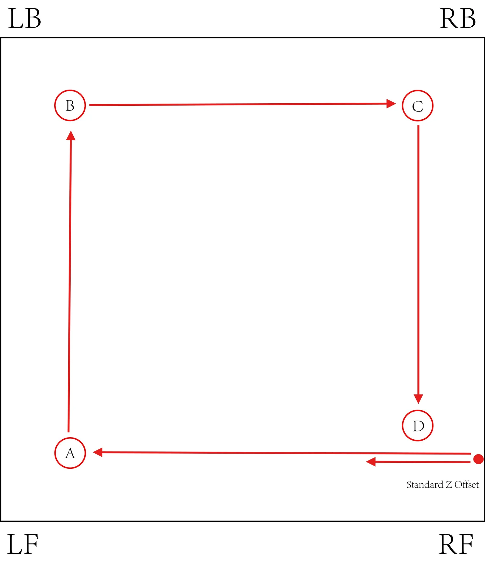
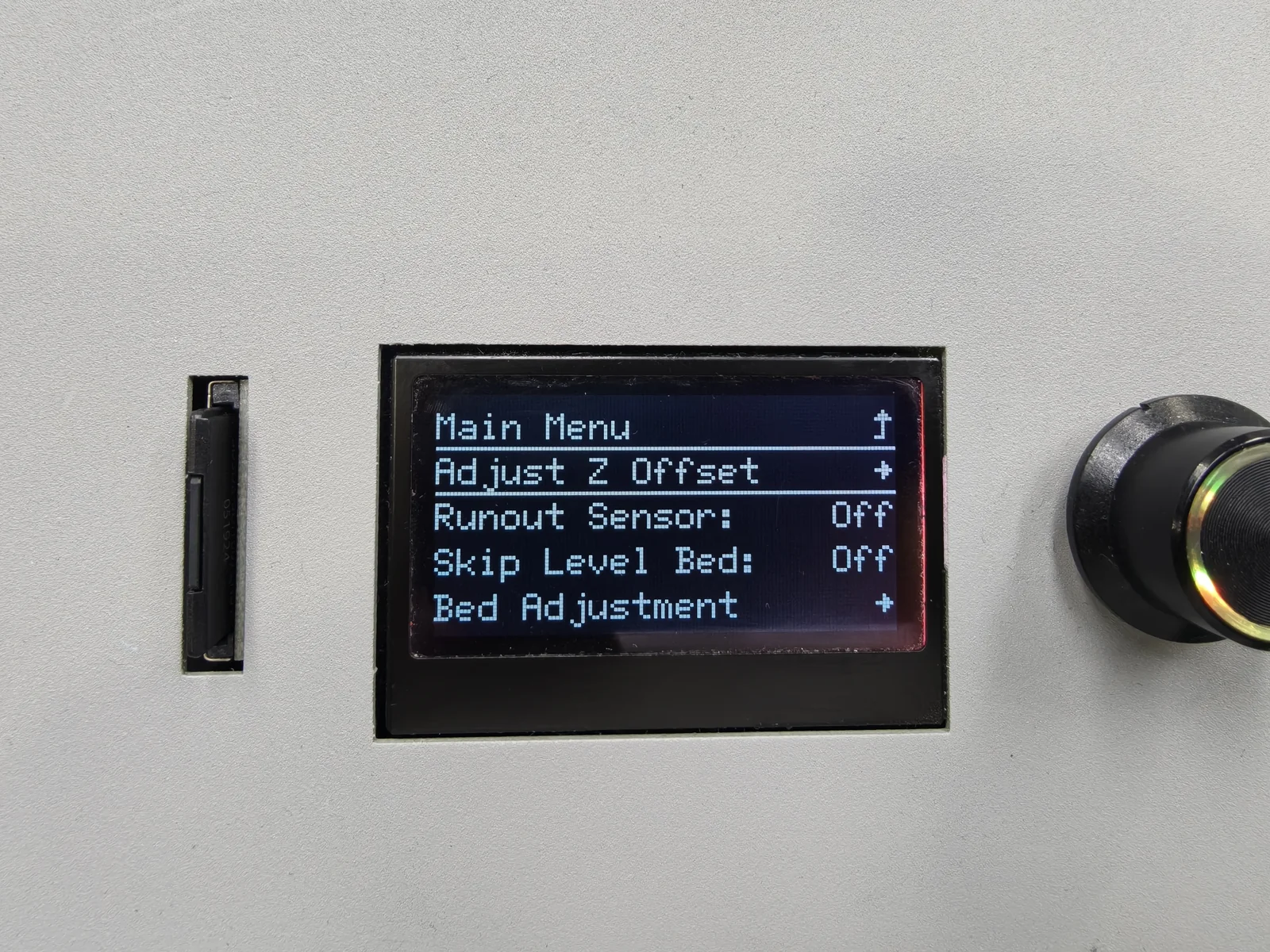
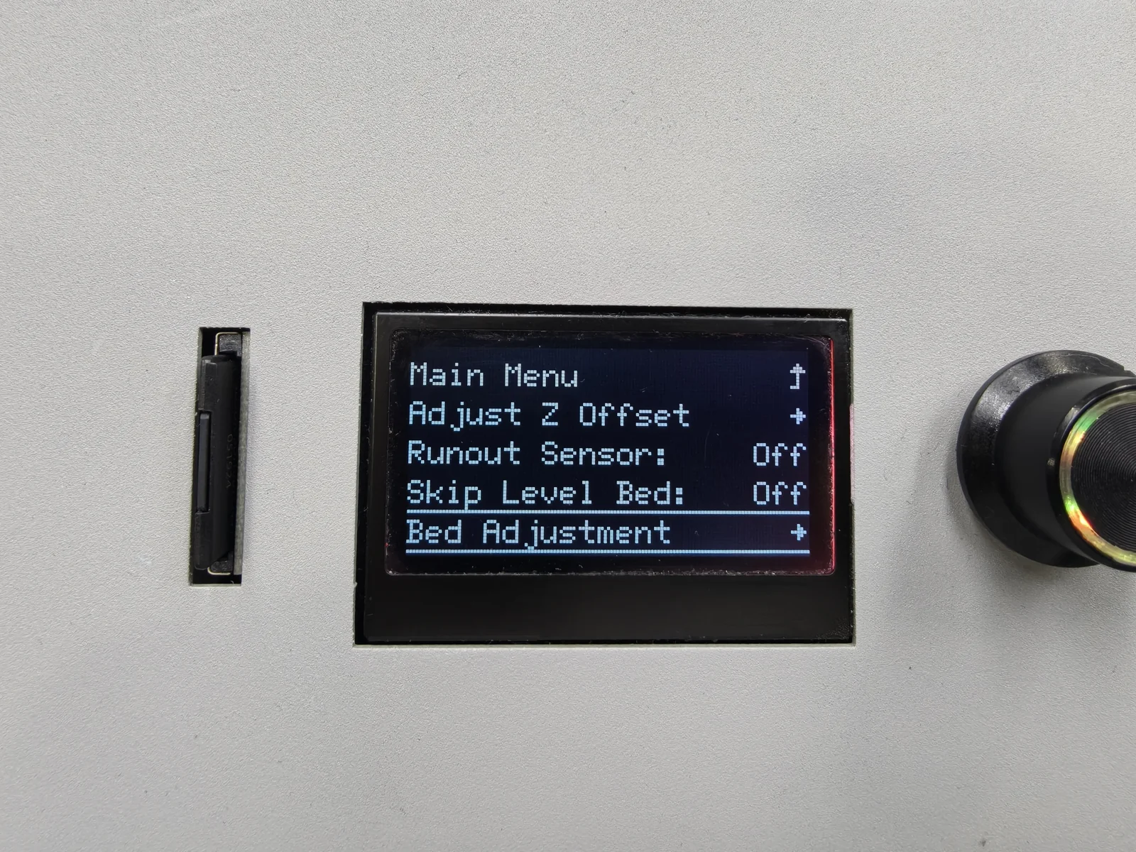
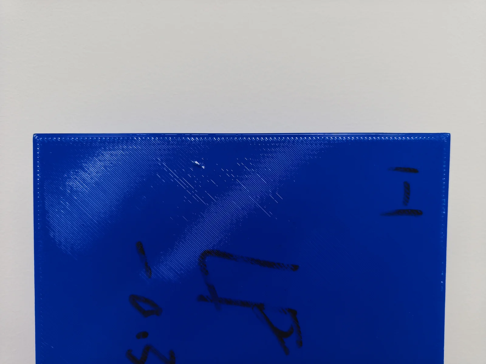
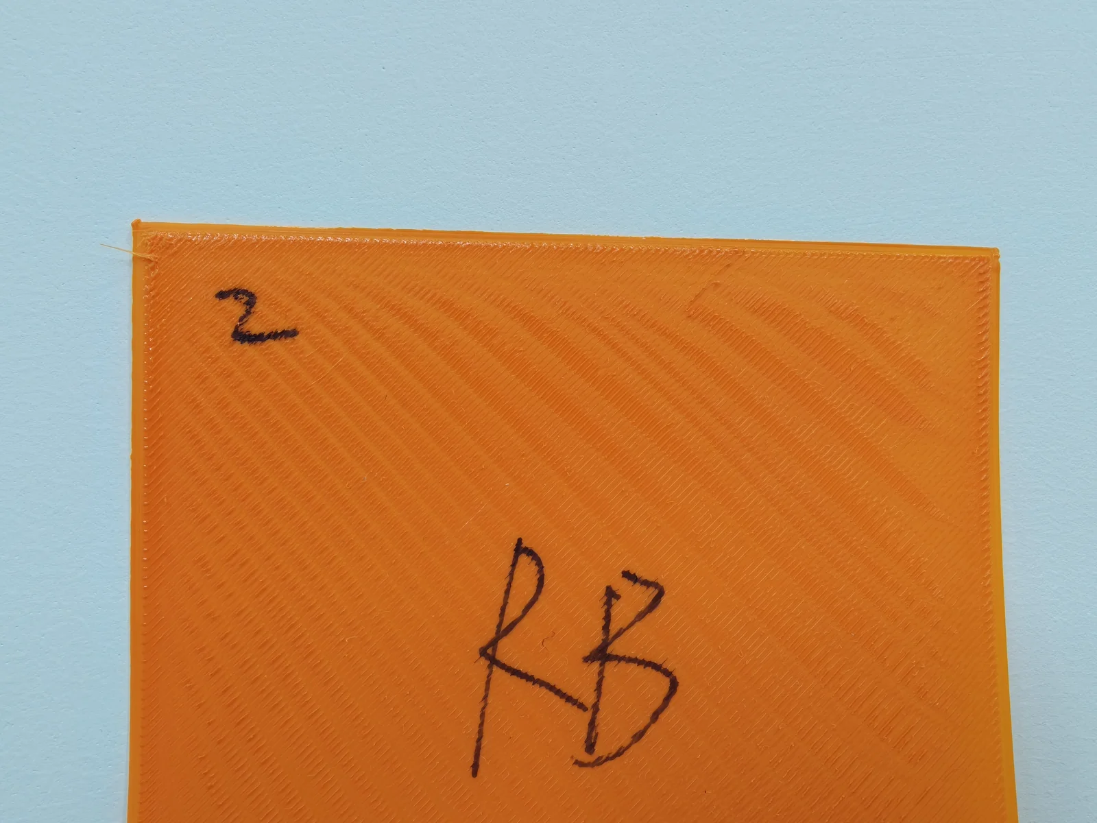
Measure the Z-offset value at the specified position of each corner of the build plate in turn. Operate as follows:
¶ 1. Step for adjusting the Z-offset value of point A
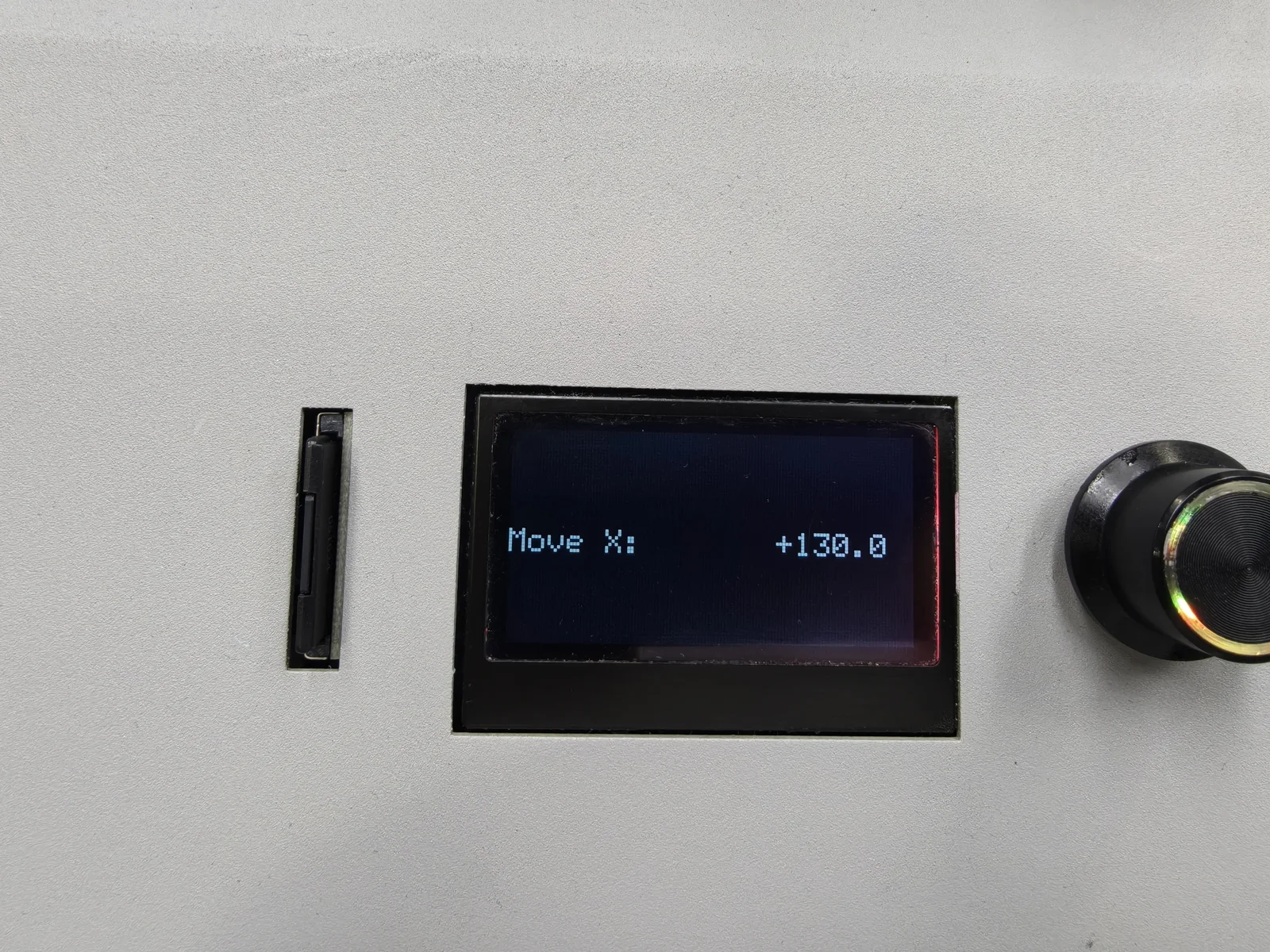
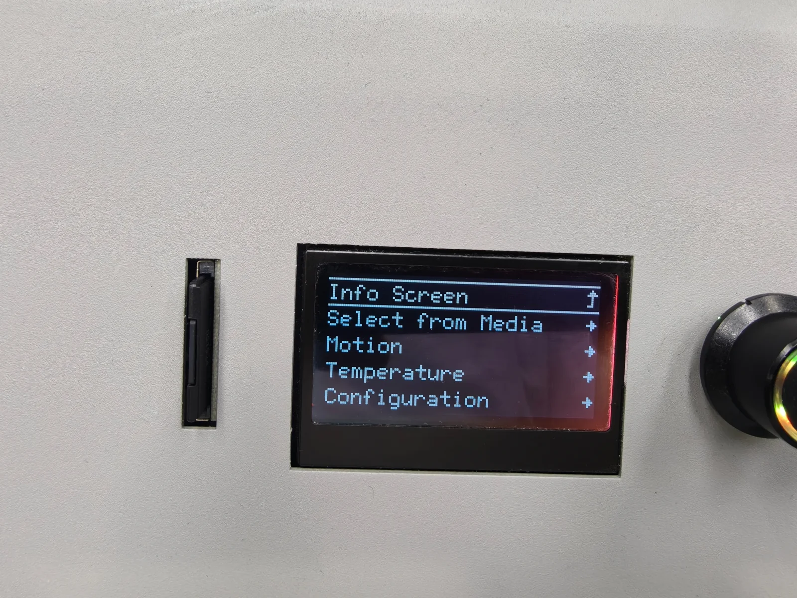
Enter the position adjustment menu: Motion - Move Axis - Move X - Move 10mm. Change the value to 130 and wait for the X-axis to move to the corresponding position.
Return to the main menu.
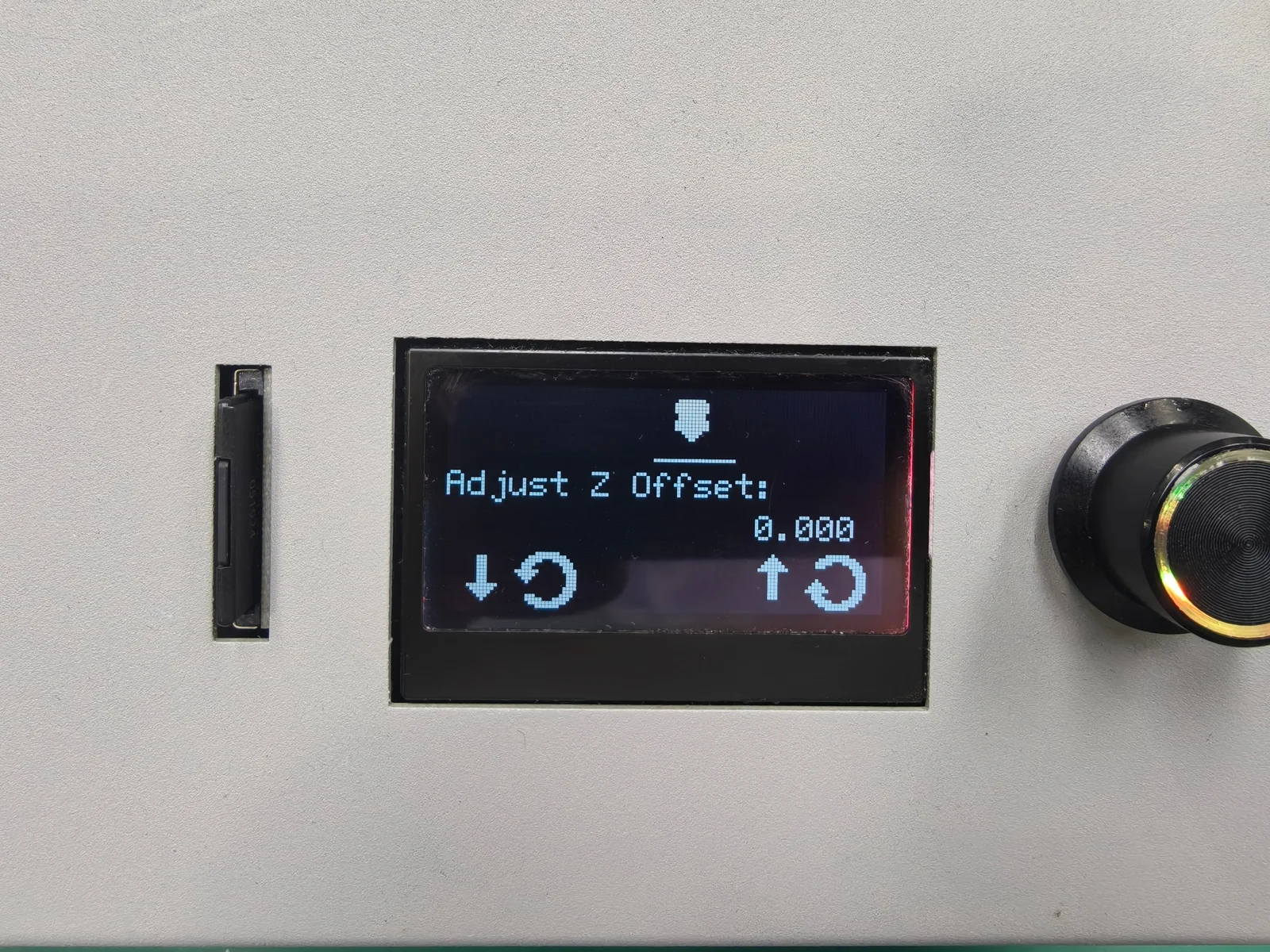
Enter the Z-offset adjustment menu: Configuration - Adjust Z-offset.
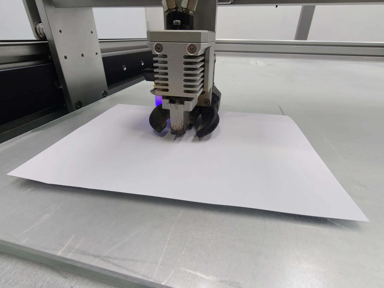
Put the Z-offset test paper under the nozzle and adjust the Z-offset value until the paper can slide but with clear resistance. Record the Z-offset value at this moment as the "A position Z-offset". (No need to enter the menu to run the Paper Test.)
After recording the "A position Z-offset", set the Z-offset value back to 0.
Return to the main menu.
¶ 2. Step for adjusting the Z-offset value of point B
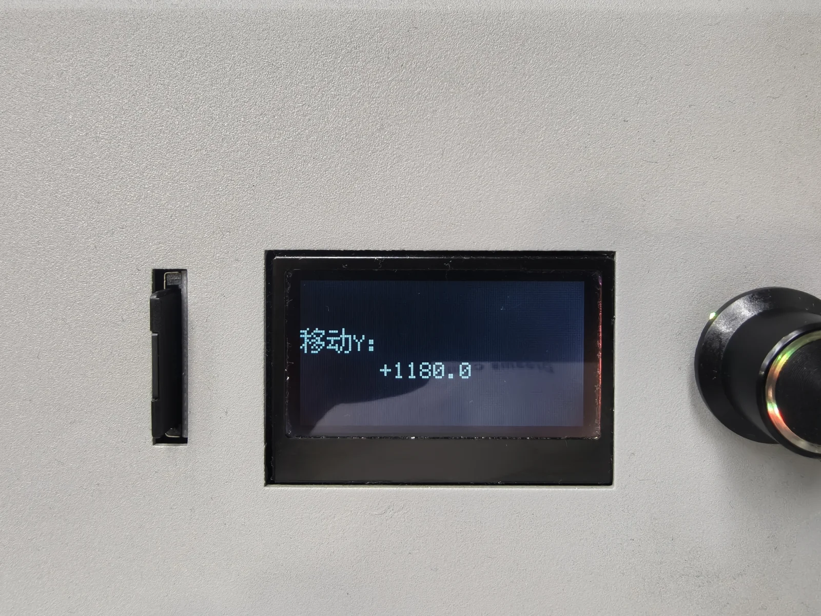
Enter the position adjustment menu: Motion - Move Axis - Move Y - Move 10mm. Change the value to 1180 and wait for the Y-axis to move to the corresponding position.
Enter the Z-offset adjustment menu again: Configuration - Adjust Z-offset.
Put the Z-offset test paper under the nozzle and adjust the Z-offset value until the paper can slide but with clear resistance. Record the Z-offset value at this moment as the "B position Z-offset". (No need to enter the menu to run the Paper Test.)
After recording the "B position Z-offset", set the Z-offset value back to 0.
Return to the main menu.
¶ 3. Step for adjusting the Z-offset value of point C
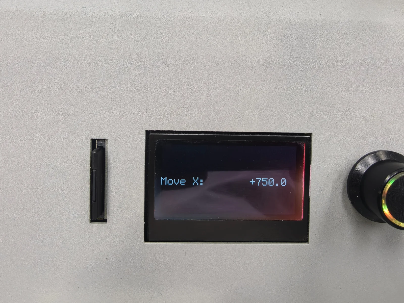
Enter the position adjustment menu: Motion - Move Axis - Move X - Move 10mm. Change the value to 750 and wait for the X-axis to move to the corresponding position.
Enter the Z-offset adjustment menu again: Configuration - Adjust Z-offset.
Put the Z-offset test paper under the nozzle and adjust the Z-offset value until the paper can slide but with clear resistance. Record the Z-offset value at this moment as the "C position Z-offset". (No need to enter the menu to run the Paper Test.)
After recording the "C position Z-offset", set the Z-offset value back to 0.
Return to the menu interface.
¶ 4. Step for adjusting the Z-offset value of point D
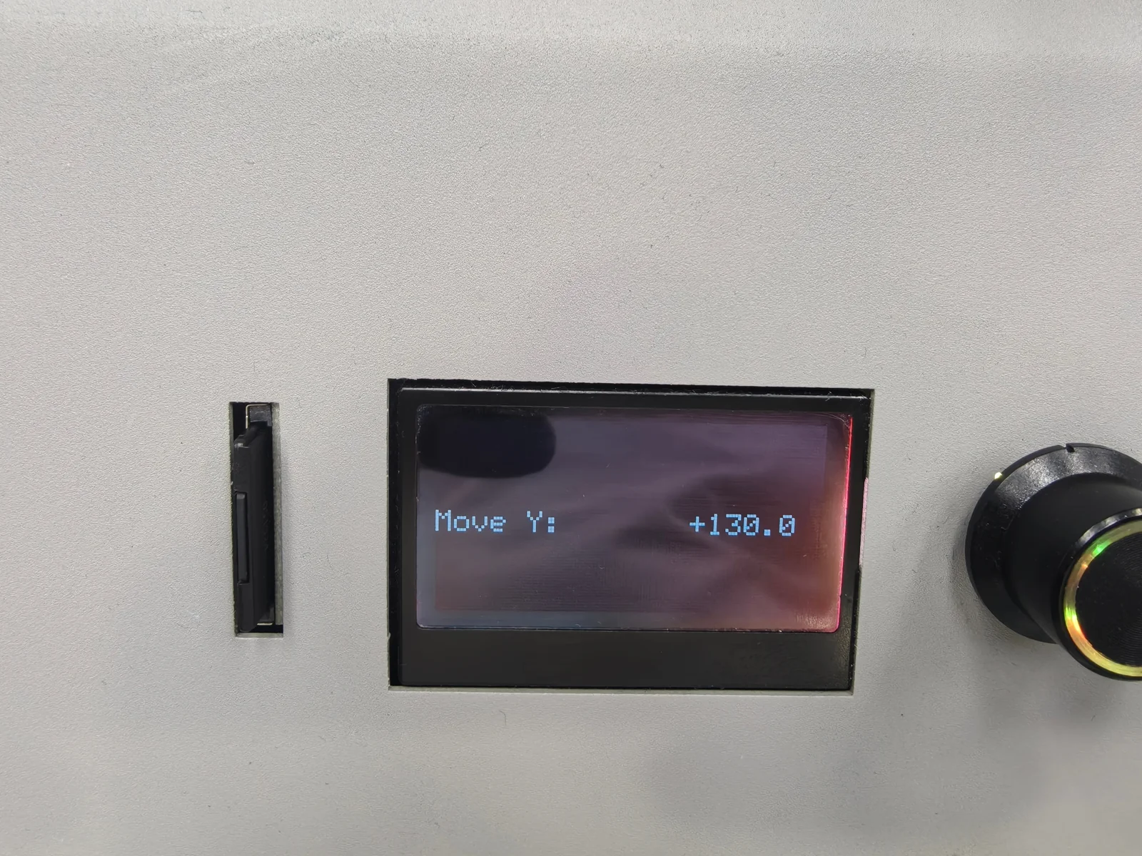
Enter the position adjustment menu: Motion - Move Axis - Move Y - Move 10mm. Change the value to 130 and wait for the Y-axis to move to the corresponding position.
Enter the Z-offset adjustment menu again: Configuration - Adjust Z-offset.
Put the Z-offset test paper under the nozzle and adjust the Z-offset value until the paper can slide but with clear resistance. Record the Z-offset value at this moment as the "D position Z-offset". (No need to enter the menu to run the Paper Test.)
After recording the "D position Z-offset", set the Z-offset value back to 0.
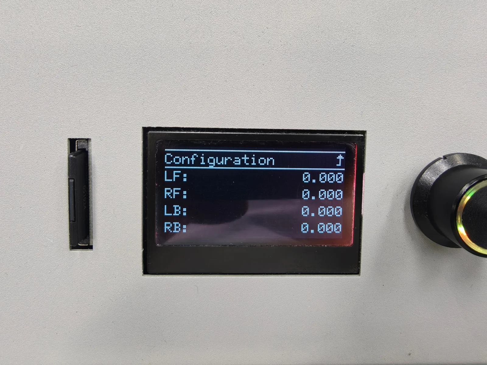
Enter the Z-offset adjustment menu again: Configuration - Adjust Z-offset.
Fill in the "Standard Z-offset" value recorded in Step 1.
In this photo, the value has not been filled in yet.
Exit this interface.
¶ Step 3: Calculate the Z-offset difference of the four corners
Subtract the "Standard Z-offset" value obtained in Step 1 from the Z-offset value of point A, B, C and D respectively, and record the corresponding differences.
LF = "A position Z-offset" - "Standard Z-offset"
LB = "B position Z-offset" - "Standard Z-offset"
RB = "C position Z-offset" - "Standard Z-offset"
RF = "D position Z-offset" - "Standard Z-offset"
¶ Step 4: Input the four values RF, LF, LB and RB into the firmware
Insert the SD card into the SD card slot of the Speed X3, read the file and start the print test.
Note:
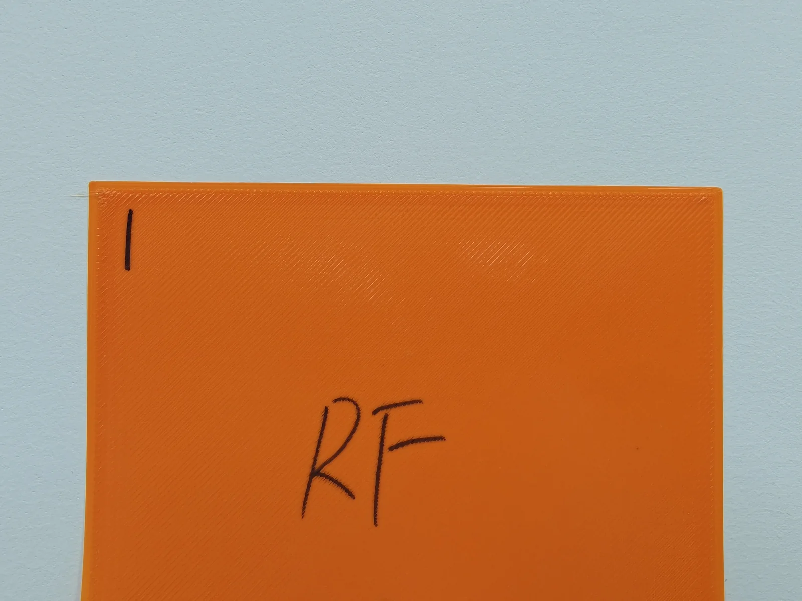
This G-code file was sliced based on "PES" filament. ⚠️ Light-tight colored filaments and metallic colored filaments must not be used for this G-code file.
Please use dark filaments of the light-transmitting series, such as blue and red, so that it is convenient to observe whether there are gaps between the lines during printing.